ENG
INE
UI
8.
Slide the cylinder block down until it botloms
on the crankcase.
9.
Install the nuts (Fig
ur
e
15
2) securing the right-
hand side
of
the cylind
er
10
the crankcase and
tighten
to
the torque specification
li
sted
in
Table 2.
10
.
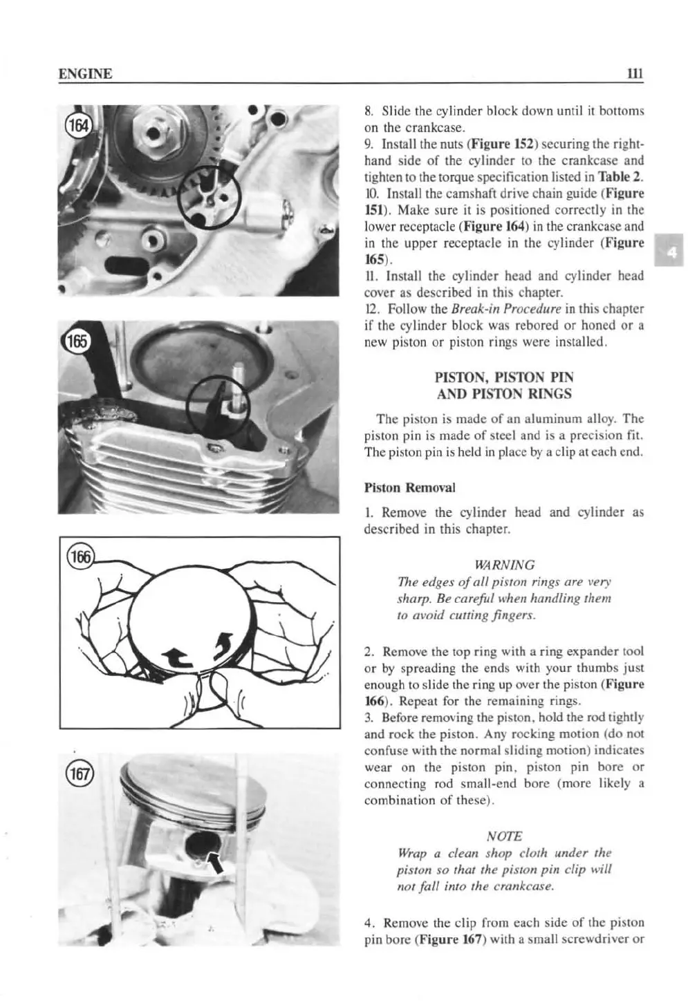
In
stall the camshaft drive cha
in
guide (l'
igur
e
151
). Make sure it is positioned correctly
in
the
lower receptacle (F
igur
e
164
)
in
the crankcase and
in
the upper receptacle
in
the cylinder (
Figure
165
).
II
. Install the cylinder head and cylinder head
cover as described
in
this chapter.
12.
Follow the Break-in Procedure
in
Ihis chapter
if
the cylinder block was rcbored
or
honed
or
a
new piston
or
pi
s
lOn
rings were insta
ll
ed.
PISTON,
PISI'ON
PIN
AND
PISTO
N RINGS
The
pislOn is made
of
an aluminum alloy. The
piston pin
is
made
of
steel and is a precision fit.
The
pi
ston pin is held
in
place by a clip at eaeh end.
Piston
Remm'
sl
1.
Remove the cylinder head and cylinder as
described in this chapter.
WARNING
TIl
e edges
of
all piston rings
art
~'ef')
'
sharp.
Be
careful
when
handling them
to avoid cuuing fingers.
2. Remove the top ring with a ring expander tool
or
by
spreading the ends with
yo
ur thumbs
jus
t
enough to slide the ring up over the piston
(F
ig
ur
e
166
). Repeat for the remaining rings.
3.
Before removing the
pi
ston. hold the rod tightly
and rock the
pi
ston. Any rocking motion (do not
confuse with the normal sliding motion) indicates
wear on the piston pin. piston pin
bore
or
connecting
rod
sma
ll
-end bore (more likely a
combination
of
these).
NOTE
Wrap
a cleol! shop cloth under the
pis/ol! so that the pistol! pill clip will
not fall into the crankcase.
4. Remove the clip from
eac
h side
of
the piston
pin bore (
Figur
e 167) with a sma
ll
screwdrive r or
 Loading...


