ELECTRICAL SYSTEM
3.
Remove the mounting scr
ew
and washer
(Fig
ur
e 76) securing the ignition switch
to
the
frame on the left-hand side.
4. Remove the switch assembly from the frame.
5.
In
stall the
new
ignition switch onto the frame
and tighten the
sc
r
ew
securel
y.
6.
Reconnect the 4-pin electrical connector. Make
su
re
the electrical connector is free of corrosion
and is tight.
7.
In
sta
ll
the seat
as
de
sc
ribed
in
Chapter Twelve.
Right-hand Combination Switch Testing
(Engine St
art
and Stop Switch
and Front Brake Light Switch)
The right-hand combination switch assembly
contains both the cngine start and engine stop
switch . The front brake
li
g
ht
switch shares
th
e
same electrical harness. but is a separate
sw
it
ch
that is connected
to
the front master
cy
linder. If
any
of the switc
he
s are faulty, then both
sw
itch
asscmblies
mu
st be replaced.
I. Remove the scat
as
described
in
Chapter
Twelve.
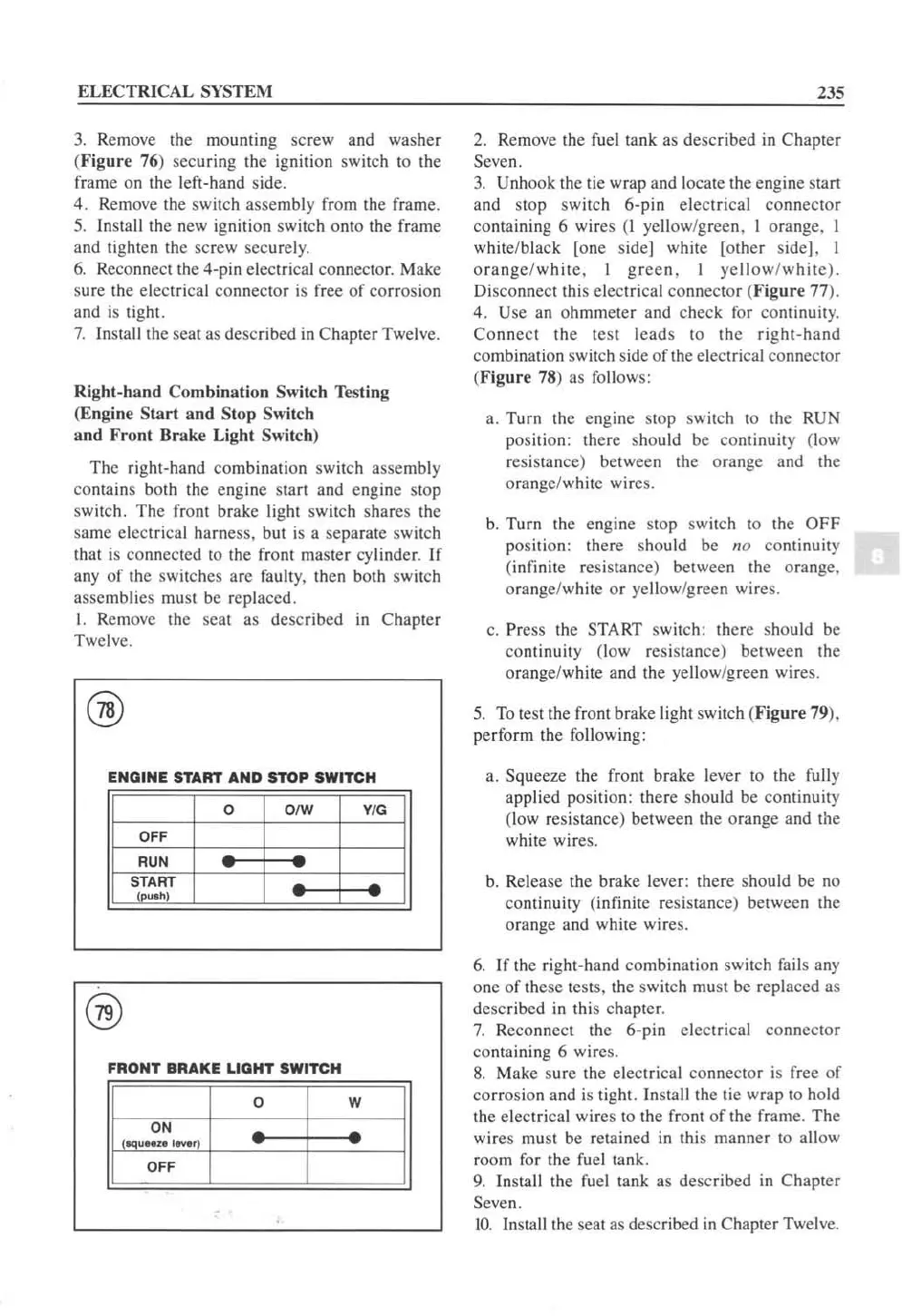
ENGINE
START
AND
STOP
SWITCH
0 O/W
V/G
OFF
RUN
~~.
RT
""
F
RONT
BRAKE
LIGHT
SWITCH
0 W
ON
(tq"Hz.I_)
O
FF
235
2.
Remove the fuel tank as described
in
Chapter
Seven.
3.
Unhook the lie wrap and locate the engine stan
and stop switch 6-pin electrical connector
containing 6 wires
(I
yellow/green, I orange. I
white/black lone side] white [other s
id
eJ. I
orange/white.
I
grcen,
I ye llow/
whitc).
Di
sco
nne
ct
Ihi
s electrical connect
or
(Figure 77).
4. Use
an
ohmmeter and check
for
continuity.
Connect the test leads to the right-hand
combination switch side
of
the electrical co
nne
ctor
(Figure 78)
as
fo
ll
ows:
a. Turn the engine stop switch
to
the
RUN
position: there should be continuity (l
ow
resistance) between the orange and the
orange/white wires.
b.
Turn the engine stop switch
to
the OFF
position: therc should
be
no
continuity
(infinite resistancc) between the orange.
orange/white or yellow/green wires.
c.
Press the
START
switch: there should
be
continuity (low r
es
istance) between the
orange/white and the yellow/green wire
s.
5.
To
test the front brake light switch (Figure 79).
perform the following:
a. Squeeze the front brake lever to the
full
y
applied position: there sho
uld
be continuity
(low res istance) between the orange and the
white wires.
b.
Release the brake lever: there should
be
no
continuity
(i
nfinite resistance) between the
orange and white wires.
6.
If
thc right-hand combination
sw
itch fails
any
one of these
te
sts, the switch
mu
st
be
replaced
as
described
in
this chapter.
7.
Reconnect the 6-pin electrical connector
containing 6
wi
res.
8.
Make sure the electrical co
nne
ctor is free
of
corrosion and
is
tight.
In
stall the tic wrap
to
hold
the electrical wires to the front
of
the frame. The
wires
mu
st be retained
in
this manner
to
allow
room
for
the fuel tank.
9.
Install the
fue
l tank as described
in
Chapter
Seven.
[0.
Install the seat
as
de
sc
ribed
in
Chapter Twelve.
 Loading...


