58
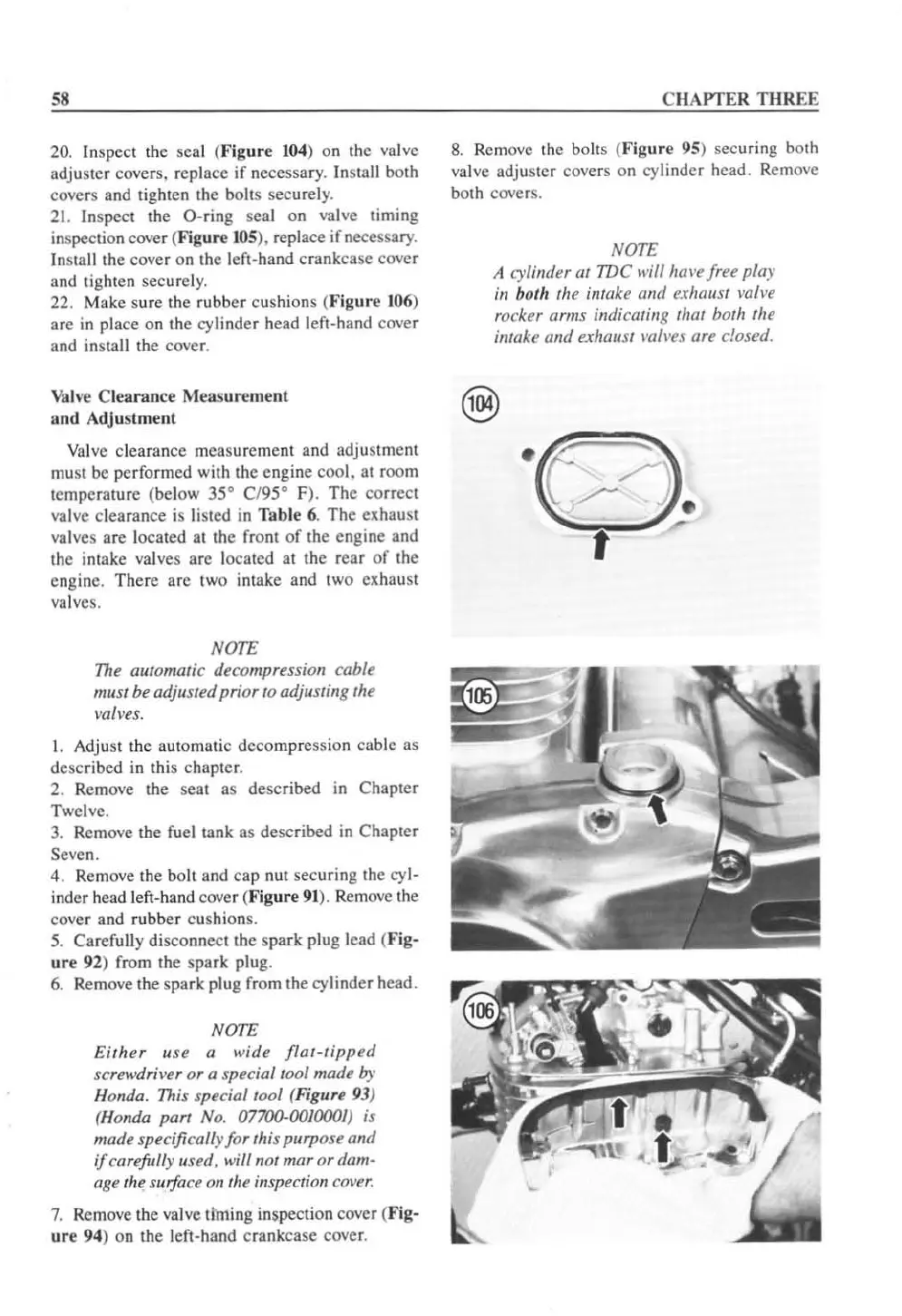
20. Inspect the seal (Figure
104
) on the valve
adjuster covers, replace
if
necessary.
In
stall both
covers and lighten the bolts securely.
21.
Inspect the O-ring seal
on
valve timing
inspection cover (
Figure
lOS
). replace
if
necessary.
In
stall the cover on the left-hand crankcase cover
and tighten securely.
22. Make sure the rubber cushions (Figure
106
)
are
in place on the
cy
linder head left-hand cover
and insta
ll
the cover.
Valve
Clearance Measurement
and
Adjustment
Valve clearance measurement and adjustment
must be performed with the engine
cool.
al
room
temperature (below 35
0
C/95° F). The correci
va
lve clearance is
li
sted
in
Table 6. The clthaust
va
lves are located at the front
of
the engine and
the
in
take
va
lves
are
located at the rear
of
the
engine. There arc two intake and two exhaust
valves.
NOTE
The
automatic decompression cable
must be adjusted prior to adjusting the
mlves.
1.
Adjust the automatic decompression cable as
described
in
this chapler.
2. Remove the seat as described in Chapter
Twelve.
3.
Remove the fuel tank as described
in
Chapter
Seven.
4. Remove the bolt and cap nut securing the cyl-
inder head left-hand cover (Figure
91
). Remove the
cover and rubber cushions.
5.
Carefu
ll
y disconnect the spark plug lead (
Fig-
ur
e 92) from the spark plug.
6.
Remove the spark p
lu
g from the cylinder head.
NOTE
Either
u
se
a
wide
ffat-tipped
screwdriver
or
a special tool made by
Honda. This special tool (Figure 93)
(Honda part No.
07700-00100(1) is
made specifically for this purpose and
if
carefully used, will not mar
or
dam-
age
th
e surface
011
th
e inspection
cover.
7.
Remove the valve liming inspection cover (Fig-
ur
e
94
) on the left-hand crankcase cover.
CHAPTER
THREE
8.
Remove the bolts (
Figure
95) securing both
valve adjuster covers on cylinder head. Remove
both cover
s.
NOTE
A {;)'Ii"der
at
TDC will
htn
'e
free play
ill both the inwke alld exhaust mll'e
rocker arms inl/icatjll8 that both Ihe
intake alld exhaust
I'lIII'es
are closed.
 Loading...


