210
by
the aiternalOr is rectified to direct
cur
ren!. The
vo
ltage regulator maintains the voltage to the
cleclrical load (lights. ignition. etc.)
at
a constant
voltage regardle
ss
of
varia lions
in
cngine speed and
load.
Chargi
ng System
Output
Test
Whenever charging system trouble
is
suspected.
make sure the battery is fully charged and in
good
condition before going any further. Clean and test
the banery as described
in
Chapter Three. Make
sure all elect
ri
cal connectors are tight and free
of
corrosion.
I. Star! the engi
ne
and let
it
reach normal
operat
in
g temperature. Shut off the engine.
2. Remove the seat as described
in
Chapler
Twelve.
3.
Remove both the right· and left-hand frame
cove
rs (Figure 2),
4. Conncct a portable tachometer following the
manufacturer's instructions.
5.
Turn the headlight
dimmer
switch to the
HI
position.
6.
Start the eng
in
e and let
it
id
le.
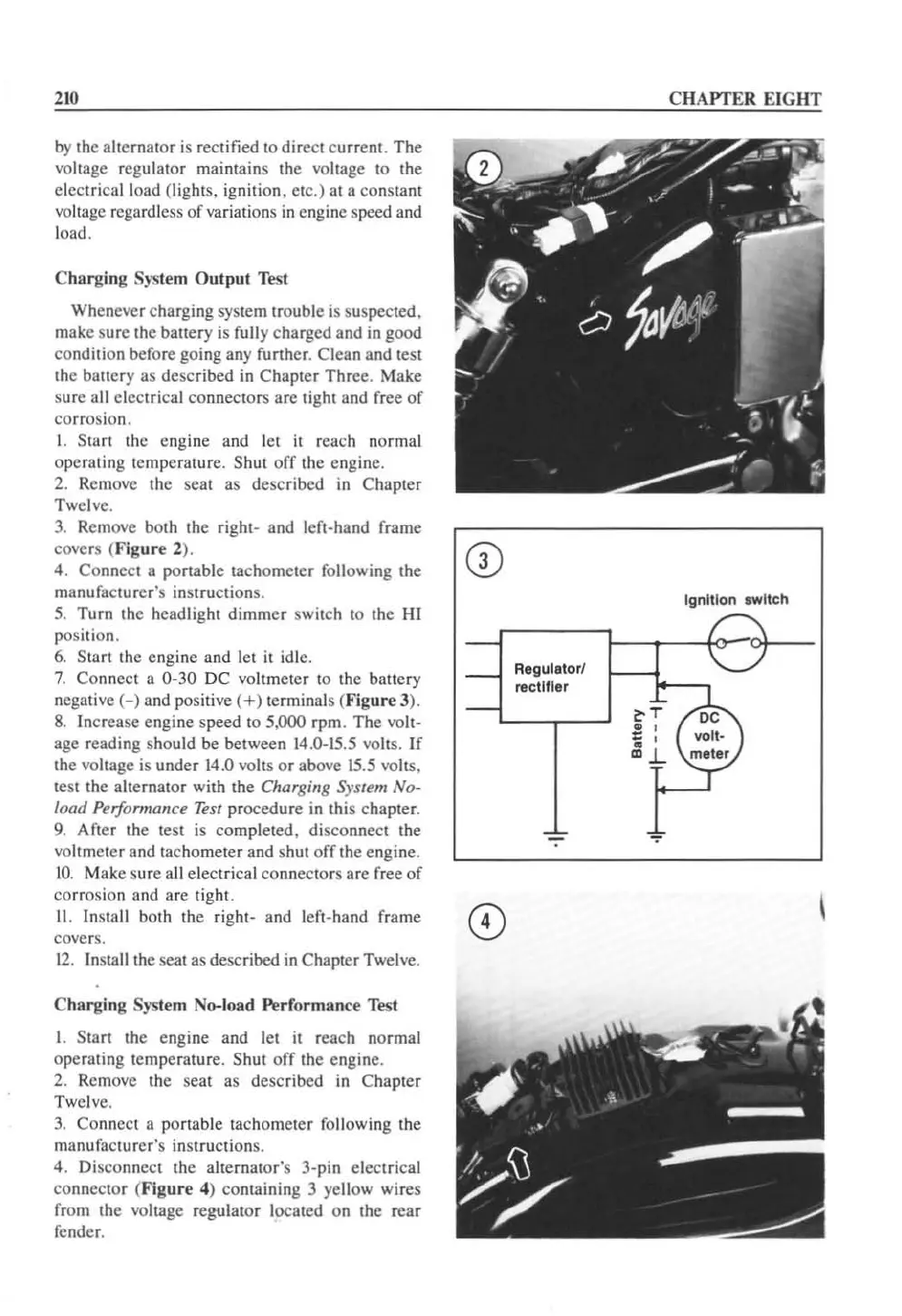
7.
Connect a 0-30 DC voltmeter to the battery
negative
(-)
and positive
(+)
terminals (
Figure
J).
8.
Increase engine speed to 5,000 rpm. The volt-
age reading should be between
14
.0-15.5 volts. If
the voltage is under 14.0 volts
or
above
15
.5 volts.
test the alternator with the Charging System No-
load
Performance
Test
procedure in this chapter.
9.
After the test is completed, disconnect the
voltmeter and tachometer and shut
off
the engine.
10.
Make sure all electrical connectors are
fr
ee
of
corrosion and are tight.
11.
Install both the right- and left-hand frame
covers.
12
.
In
sta
ll
the seat as described
in
Chapter Twelve.
Ch
arging
System No-l
oad
Performance Test
1.
Start the engine and let
it
reach normal
operating temperature. Shut
off
the engine.
2. Remove the seat as described
in
Chapter
Twelve.
3.
Co
nn
ect a portable tachometer following the
manufacturer's instructions.
4. Disconnect the alternator's 3-pin electrical
connector (
Figure
4) containing 3 yellow wires
from the voltage regulat
or
located on the rear
fender.
Regutatorl
rectilier
CHAPTER EI
GHT
tgnltlon
_I
tch
 Loading...


