266
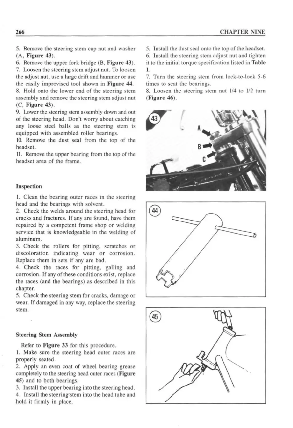
5.
Remove the steering stem cap
nUl
and washer
(A,
Fig
ur
e 43).
6.
Remove the upper fork bridge (B. Figu
re
43
).
7.
Loosen
the
sleeri
ng
stem
adjust
nUl.
To
loosen
the adjust nut, use a large drift and hammer or usc
the easily improvised
1001
shown
in
Figu
re
44.
8.
Hold
OniO
the lower end
of
the steering stem
assembly and remove the sleering stem adjust nut
(C.
Figur
e 43),
9.
lowe
r the sleering
stem
assembly
down
and
out
of
the steering head. Don'l worry about catching
any loose steel
balls as the steering stem
is
equipped with assembled roller bearings.
10.
Remove
the
dust
seal
from
the
top
of
the
headset.
II
. Remove the upper bearing
fr
om the top
of
the
headset area
of
the frame.
In
spe<:
tion
I. Clean the bearing
outer
races in the sleering
head and the bearings with solvent.
2. Check the welds around the steering head for
cracks and fractures.
If
any are found, have them
repaired
by
a competent frame shop
or
welding
service that
is
knowledgeable
in
the welding of
aluminum.
3.
Check the rollers for pining. scratches
or
discoloration indicating
wear
or
corrosion.
Replace them
in
sets
if
any are bad.
4. Check the races for pining. galling and
corrosion. If any
of
these condilions exist. replace
the races (and the bearings) as described in this
chapter.
5.
Check the steering stem for cracks. damage
or
wear. If damaged
in
any
way.
replace the steering
stem.
Stee
rin
g Stem Assembly
Refer to Fig
ur
e 33 for this procedure.
1.
Make sure the steering head outer
ra
ces are
properly seated.
2. Apply an even coat
of
wheel bearing grease
completely to the steering head outer races (Figure
45) and to both bearings.
3.
Insta
ll
the upper bearing into the steering head.
4.
I
ns
ta
ll
the steering-stem
inlO
the head tube and
hold
it
firmly
in
place.
CHAPTER
NINE
5.
I nstall the dust seal
Onto
the top
of
the headset.
6.
Install the steering stem adjust nut and tighten
it
to the initial torque specification
li
sted in Table
I .
7.
Turn the steering Stem from lock-to-lock
5·6
times
10
seat the bearings.
8.
Loosen the steering stem nut
114
to
112
turn
(Fi
gu
re 46).
®
 Loading...


