118
1
0.
In
stall the thrust washer (
Figure
188) and the
dri
ve
pin (
Figure
)87).
11
. Align the notch
in
the oil pump drive sprocket
with the drive pin and
in
sta
ll
the o
il
pump drive
sprock
et
(
Figure
186)
onto
the oil pump.
12
. Pull up on the shaft and install the circlip
(Figure
185
) securing the oil pump driven sprocket
to the o
il
pump. Make s
ur
e the circJip is properly
seate
d in the shan groove.
13.
Assemble the crankcase as described
in
this
chap
ter.
Inspection
Replacement parts a
rc
not
avai
la
ble for
th
e oil
pump.
If the
oi
l pump
is
nOI
opcr
aling prope
rl
y.
th
e entire oil pump assem
bl
y
mu
st be replaced.
CAIJTION
Do
liD/try
10
disassemble the
oil
pump
as replacement parts
lI/1d
iockwlIshers
are
nOI al'ailable.
I. ROlate the drive shaft (
Figure
190). If there
is
any binding
or
signs
of
wear: replace the o
il
pump
assembly.
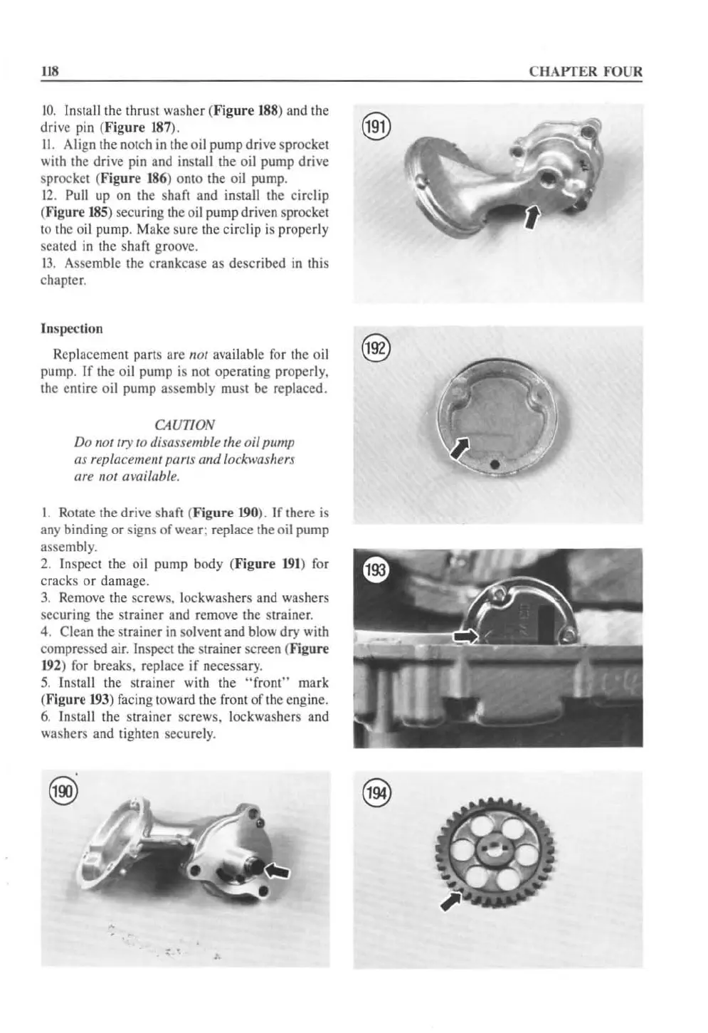
2.
In
spect the oil pump body (
Figure
191)
for
cracks or damage.
3.
Remove the screws. lock
wa
shers and washers
securing the strainer and remove the strainer.
4. Clean the strainer
in
so
lv
ent and blow dry with
compressed air.
In
spect the
st
rainer screen (Figure
192
) for breaks. replace if necessary.
5.
Install the str
ai
ner with the
"front"
mark
(Figure
193
) fac
in
g toward the front
of
the en
gi
ne.
6.
In
stall the strainer screws. lock
wa
shers and
washers and tighten securel
y.
, .
CHAPTER FOUR
 Loading...


