238
4. Remove the screws securing the left-hand
combination switch toge
th
er a
nd
remove the switch
as
se
mbly (Figure 85
).
5. Remove the e
le
ctrical wire harness from any
clips on the frame and carefully pull the harness
OUI
from the frame.
6. Ins
ta
ll
a new switch and lighten the screws
securely. Do nOI overtighten the screws or the
plastic switch housing may crack .
7.
Reco
nn
ect the
IO
-pin electrical connector. the
2 individual wire connectors and the one to the
horn.
8. Make sure the electrical
co
nn
eclO
rs arc
fr
ee
of
c
orro
sion and 3rc
ti
g
ht
.
In
S
lal1
the tie wrap to hold
the electrical wires to the front of the frame. The
wires must be retained in this m::lnncr 10 allow
room f
or
th
e fuel tank.
9.
In
stall the fucl tank as desc
ri
bed
in
Chapter
Seven.
10. Ins
la
llth
e seat as described in Chapter Twclvc.
S
tarter
Interlock Switch
(Clutch Lever) Testing
1.
Remove the scat as described in Chapter
Twelve.
2. Remove the fuel tank as
in
Chapter Seven.
3.
Unhook the tie wrap and locate the starter
interlock
switch's 2 individual
ye
ll
ow/green wires.
Di
sco
nn
ect these 2 individual electrical connectors
(
fi
g
ure
81
).
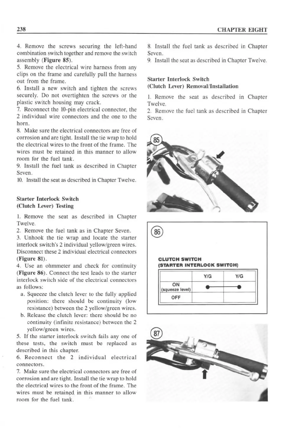
4. Use an ohmmeter and check for continuity
(
Fi
g
ure
86). Connect the test leads to the starter
interlock switch s
id
e of the electrical connectors
as follows:
a. Squeeze the clutch lever
to
the fully applied
pos
it
io
n:
there should be
co
nt
in
uity (low
resistance) between the 2
ye
llow/green wire
s.
b. Release
th
e clutch lever: there should
be
no
co
ntinuity (infinite resistance) between the 2
ye
ll
ow/g reen
wi
re
s.
5.
If the start
er
interlock switch
fai
ls
anyone
of
these tests. the sw
it
ch must be replaced as
described
in
this chapter.
6. R
eco
nne
ct
the
2
individual
el
ectrical
co
nn
ectors.
7.
Make sure the electrical connectors are free
of
corrosion and
ar
e
ti
ght.
In
sta
ll
t
he
tie wrap to hold
the elect
ri
cal wi
re
s
to
the front of the frame.
Th
e
wires must be retained in this man ner to a
ll
ow
room for the fu
el
tank.
CHAPTER EIGHT
8.
Install the fucl tank as dcscribed
in
Chapler
Sevcn.
9.
Install thc seat as described in Chapter Twclve.
S
tarl
er
In
ter
lock
Sw
itch
(Clutch
Le
"er) Remm'
II
I/ln
sta
ll
ation
I. Re
mov
e the seat as desc
ri
bed in C
ha
pter
Twelve.
2. Remove the fuel tank as described
in
Chapler
Seven.
@
CLUTCH
SWtTCH
(STARTER
INTERLOCK
SWITCH)
YIG YIG
ON
1l
'.aue
ere
leve
'
II
OFF
 Loading...


