CLUTCH
@
, .
155
II
.
In
spect the damper
spr
in
gs (
Figure
25). If they
afC
sagged
or
broken the QUier housing
mu
st
be
replaced.
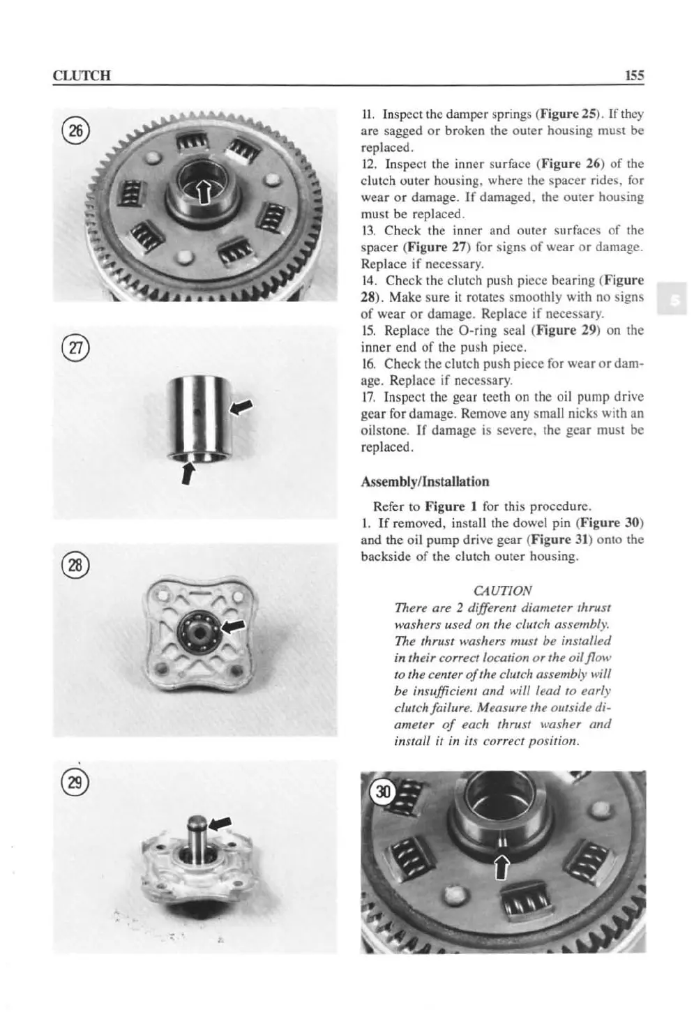
12
.
In
s
pe
ct the inner surface (Fig
ur
e 26)
of
the
clutch outer hou
si
n
g.
where the spacer rides. for
wear
or
damage.
Ir
damaged. the ouler housing
must
be
replaced.
1
3.
Check the inner and out
er
surfaces of the
spacer (
Figure
27) for signs
of
wear
or
damage.
Replace if necessary.
14.
Check the clutch push piece bearing (Fig
ur
e
28). Make sure
it
rotates smoothly with no signs
of
wear
or
damage. Replace
if
necessary.
1
5.
Replace the O-ring seal (Figure 29) on the
inner cnd
of
the push piece.
1
6.
Check the clutch push pie
ce
for wear
or
dam-
age. Replace
if
necessary.
1
7.
Inspect the gear teeth on the oil pump drive
gear for damage. Remove any small nicks with an
oilstone. If damage is severe. the gear must
be
replaced.
Assemblyf
In
sta
ll
ation
Refer to
Figure
1 for this procedure.
I. If removed, insta
ll
the dowel pin (
Figure
30)
and the oil pump drive gear (
Figure
31
) onto the
backside
of
the clutch outer housing.
CAUTION
There are 2 different diameter thrust
washers used on the clut
ch
assembly.
The thrust washers
mllst be installed
in their correct location
or
the
oilflow
to
the center
of
the clutch assembly
lI'ill
be insufficient alld will lead
to
early
clutch failure. Measure the outside
di-
ameter
of
each thrust washer
and
ins
ta
ll it
in
its correct position.
 Loading...


