214
14.
Ti
ghten the cover bolts securely.
WARNING
Be
sure
10
secure the alternator
e/eclri
caJ
cable
and
emission control
hoses back to the frame as shown
in
Fi
gure
/0.
If
the electrical cable is not
secured as shown, it will more orer and
the drive
belt
wj{f
rub on it.
Th
e drive
bell
will wear (llrollgh Ihe insulation
and
all
electrical short or open will
occ
ur.
1
5,
Install the tie wrap
(F
igur
e
10
) securing the
alternator electrical cable and emission control
hoses
to
the frame.
16.
Make sure the electrical co
nn
ector
is
free
of
corrosion and
is
tight.
17.
Fill the engine with the recommended type and
quantity of oil as described und
er
Engine Oil and
@4
Filter Change in Chapter Three.
Rotor Testing
The rotor
is
permanently magnetized and cannot
be
tested except
by
replacement of a rotor known
to
be
good. A rotor can
lo
se magnetism fr
om
o
ld
age
or
a sharp blow. If defective, the rotor must
be
replaced: it cannot be remagnetized.
Rotor Removal/Installation
NOTE
This
procedure
is
shoWTJ
with the
engine remove frolll the
frame
and
partially disassembletl
for
clarity. It is
not necessary to remove the engine to
remove the rotor assembly.
\.
Remove
the stator assembly
as
described in this
chapter.
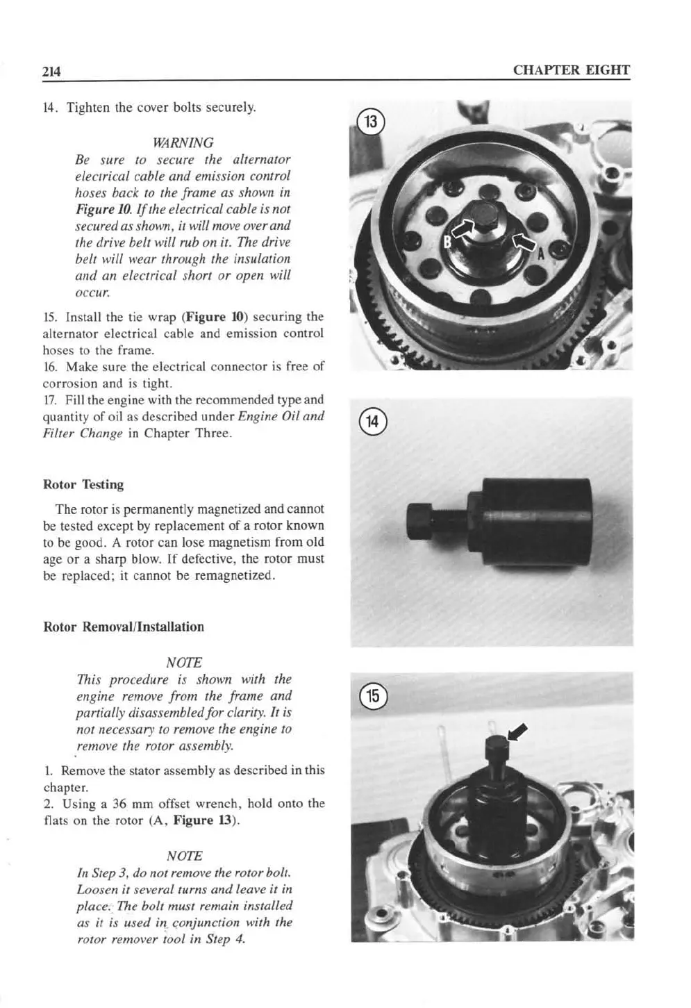
2.
Us
in
g a 36
mm
of
fset
wrench, hold onto the
Oat
s on
th
e rotor (A. Figure
13
).
NOTE
In
Step
3,
do
not
remo~'e
the rotor bolt.
Loosen it
severallll
rns
and
leave it in
place. The
bolt
must remain installed
as
it is usetl
in
(o
njunction with the
rotor
remover tool in Step
4.
CHAPTER EIGHT
 Loading...


