88
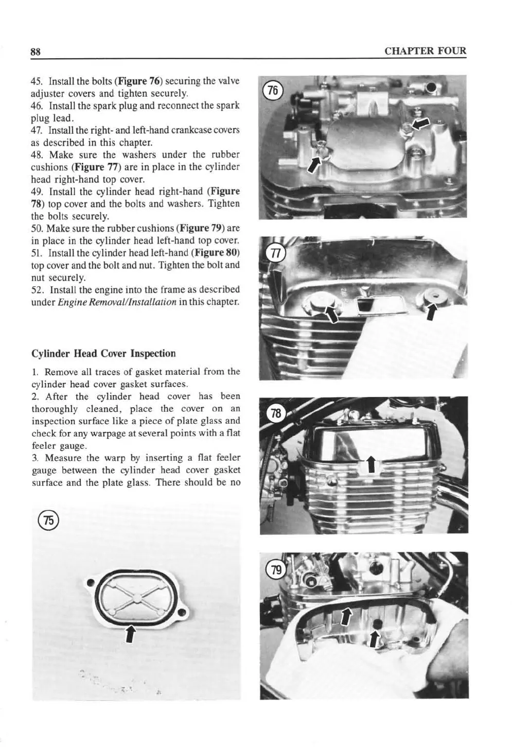
45. Install the bolts (
Figure
76
) securing the
va
l
ve
adjust
er
covers and tig
ht
en securel
y.
46. Install the spark plug and reconnect the spark
plug lead.
47. Install the
ri
ght- and left-hand crankcase covers
as
described in this chapter.
48.
Make sure the washers under
th
e rubber
cushions (Figure 77) arc in place
in
the cylinder
head right-ha
nd
top cover.
49.
In
stall the
cy
linder head
ri
ght-hand (
Figure
78) top cover and the bolls and washers. Tighten
the bolts
sec
ur
el
y.
5
0.
Make s
ur
e the rubb
er
cushions (
Fig
ur
e 79) are
in
place
in
the cy
linder
head left-hand
lOp
cover.
51. Install the cylinder head left-hand (
Figure
80
)
top cover and the bolt a
nd
nut. Tighten the bolt and
nut securel
y.
52. Insta
ll
the cngine into the frame as described
under Engine Removal/
In
stallation
in
this chapter.
Cylinder Head Cover Inspection
I. Remove all traces
of
gasket material from
th
e
cyl
inder head cover gasket
su
rfaces.
2.
A
ft
er the
cyl
inder head cover has been
thoroughly cleaned, place
th
e cover on an
inspection
su
rface like a piece
of
plale g
la
ss and
check for any warpa
ge
at several points with a flat
feeler
ga
uge.
3.
Measure the warp
by
inse
rt
ing a flat feeler
ga
u
ge
between
th
e cylinder head cover gasket
surface and the plate glass. There should
be no
, .
,.
CHAPTE
R FOUR
 Loading...


