FRO
NT
SUSPE
NS
I
ON
AN
D STEE
RI
NG
®
@
®
265
by the holders.
The
holders should also be kept
clean and rrce
or
any metal that may ha\'c been
gougcd loose by handlebar slippage.
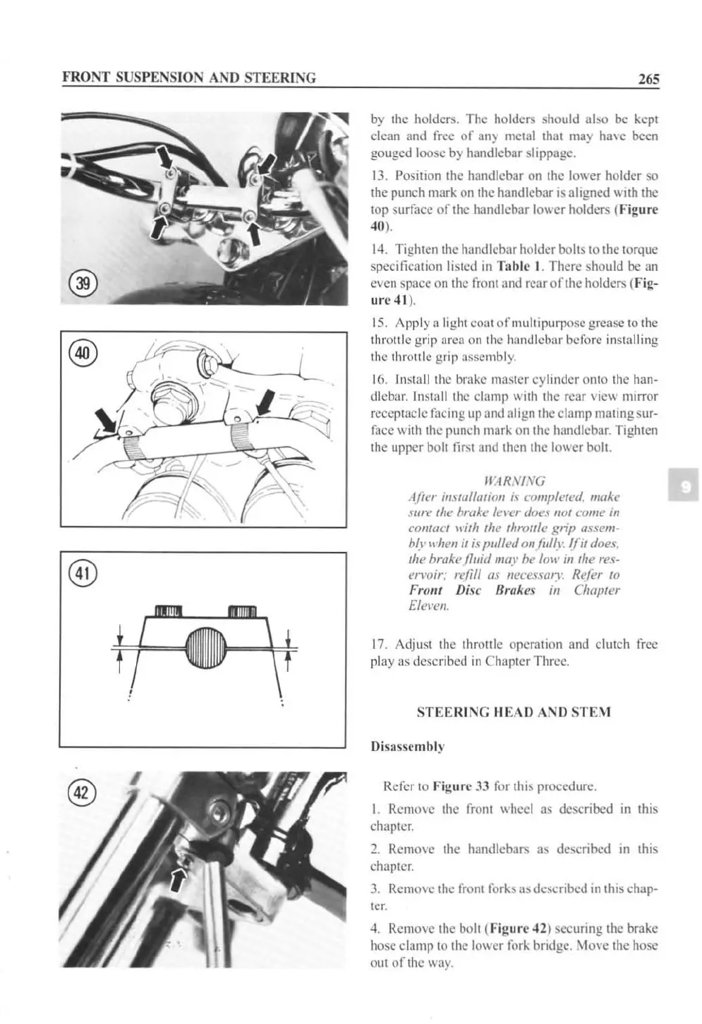
13. Position the handlebar
on
the lower holder
so
the punch mark on the handlebar is aligned with the
top surrace
or
the handlebar lower holders (Figu r
('
'0
).
14.
Tighten the handlebar holder bolts to the torque
specification listed
in
Table
I.
There should be an
even space on the rront and rear
or
the holders (Fig-
ur
e
41
).
15.
App
lya
light coat
or
multipurpose grease to the
thr
Oll
lc gr
ip
area on the hlllldlcbar bcrore insta
ll
ing
thc
th
r
Ol1le
grip assembly.
16.
In
stall the bmke master cylinder onto the han-
dlcb:lr. Instli
llt
he clamp with the rear
dew
mirror
recepTacle racing up and align the clamp mating
sur-
race with the punch mark on the handlebar. Tighten
the upper bolt
firsT
and
Then
the
lo\\er
boll.
WARNING
After il/slt//lariol/
if
cO
II/I)/e
rni
. make
slIn'
rhe
hrllkl'
/el'l'I'
doel'
/lor
cO
llie
ill
cOIIUtcr
lI'irh
rhe
rhrorr/e
grip lIssell/-
b(I'
II'hen
ir
is
pulled ollfil/(l: Ifir does.
rhe
brake jll1id
lIIay
be
loll' ill
rhe
res-
en'oir:
I¥.'jill
as
lIe
cesl'{/rT Refer
to
From Dis
£'
Brakes
ill
Chaprer
Elel'l!lI.
17. Adjust the thro
tt
le opcrtllion and clutch rree
play as described
in
Ch(lpt
er
Thrcc.
STEE
RI NG I·IEAO AND ST
EM
Disassembly
Rerer
10
Figurl' 33 ror this procedure.
I.
Remme
the rront wheel as described
III
this
chapler.
2.
Relllo\e the handlebars as described
in
thi
s
chaplcr.
3.
RClllo\ c Ihc
rr
o
nt
rorks as dcscribed
in
thi
s chap-
te
r.
4. Remo."c the bolt (Fig
ur
l' 42) securing the brake
hose clamp
10
the lower rork bridgc. Movc thc hose
out
oft
hc
\H
ly.
 Loading...


