236
Ri
ght-hand Combination Switch
Removal/l nstallation
(Engine
Start
and
SlO
p Switch
and Front Brake Light Switch)
The right-hand combination sw
it
ch assembly
contains
both the engine start and engine stop
switch. The fronl brake light switch shares the
same electrical harness, but
is
a separate switch
connected to the front master
cy
linder. If any
of
the switches arc faulty. both switch assemblies
must be replaced.
1.
Remove the scal as described in Chapter
Twelve.
2. Remove the fuel tank as described
in
Chapter
Seven.
3.
Unhook the tie wrap and locate the engine Slart
and stop switch
6-pin
electrica
l connect
or
containing 6 wires (I yellow/g
re
cn.
I orange. 1
white/black [one s
id
e]
white [other side). I
o
ran
ge/w
hit
e.
1 gr
een,
I
yellow
/
white).
Disconnect this electrical
con
nector (
Figure
77).
4. Remove the screws securing the front brake
light switch
to the front master cy
li
nder and remove
the electrical wires from
th
e switch assembly.
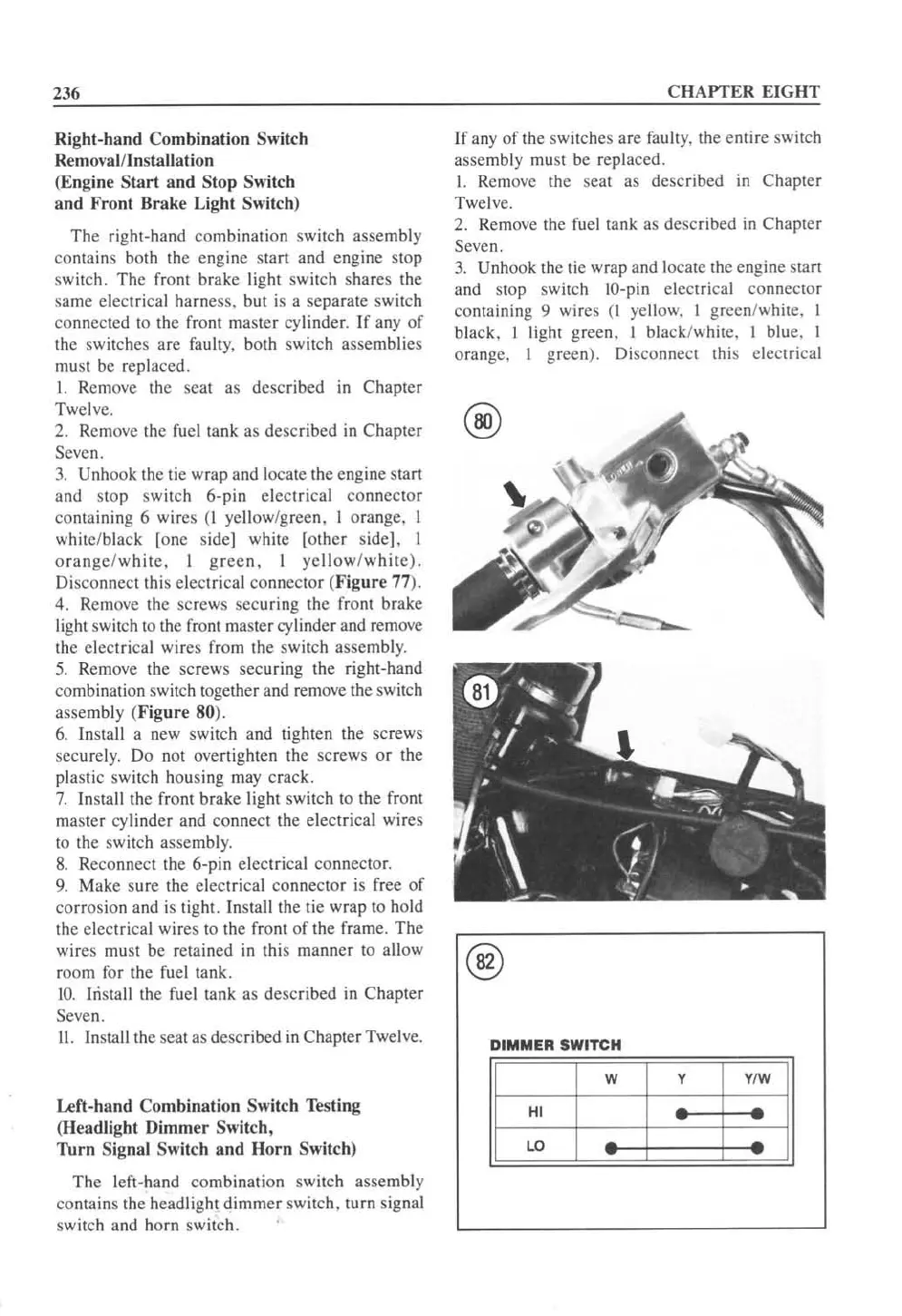
5.
Remove the screws securing the right-hand
combination switch together and rem
ove
the sw
it
ch
assembly (
Figure
80
).
6.
Install a new switch and tighten the screws
securel
y.
Do not overtighten the
sc
rews
or
the
plastic switch housing may crack.
7.
Install the front brake light switch to the front
master cyl
in
der
and
con
nect the electri
ca
l wires
to the switch assembl
y.
8.
Reconnect the 6-pin electrical connector.
9.
Make sure the electrical connector is fr
ee
of
corros
ion and is tight.
In
stall the tie wrap to hold
the electrical wires to the front
of
the frame. The
wires must be retained in this manner to allow
room for the fuel tank.
iO.
Iristall the
fu
el tank as described in Chapter
Seven.
II.
Install the seat as described
in
Chapter Twelve.
Left-hand
Co
mbination
Sw
itch Testing
(Hea
dlight
Dimmer
Switch,
Thrn
Signal Switch
and
Horn
Switch)
The left-hand
comb
ination switch assembly
contains the headlight
dimmer
switch, turn signal
switch and h
orn
sw
it
ch.
CHAPTER
EI
GHT
If any
of
th
e switches arc fau lty. the entire switch
assembly must be replaced.
I. Remove the seat as described
in
Chapter
Twelve.
2. Remove the fuel tank as described in Chapter
Seven.
3.
Unhook the tie
wrap
and locate the engine start
and stop switch IO-pin electrical connector
containing 9 wires
(I yellow. I greenJwhite. I
black. I light gr
een,
I black/white. I blue. I
orange. I green). Disconnect this electrical
@
DIMMER
SWITCH
 Loading...


