200
I. Remove the seat as described
in
Chapler
Twelve.
2. Remove the fuel lank as described in this
chapter.
3.
Remove the carburclOr as described
In
this
chapler.
4. Remove the air filter as described und
er
Air
Filter Elemertt
in
Chapler
Three
.
5.
Remove the bancry case as described
in
Chapter
Eight.
6.
Disconnect
the
cr
ankcase
breather ho
se
from
the
ai
r filter
air
box.
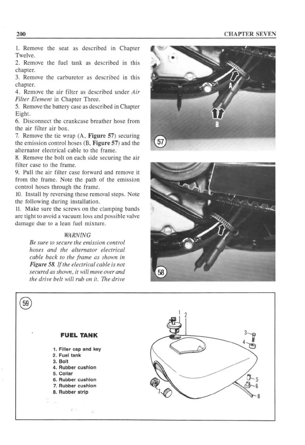
7.
Remove the tie wrap (A.
Figure
57) securing
the emission contr
ol
hoses
(8,
Figure
57) and the
alternator electrical cable to the frame.
8.
Remove the bolt on each side securing the air
filler case to the frame.
9.
Pull the
ai
r filter case forward and remove it
from the frame. Note the path of the emission
control hoses through the frame.
1
0.
Install
by
revers
in
g these removal sleps. Note
the following during
in
stallation.
II.
Make sure the screws on the
clamp
in
g bands
are
light 10 avoid a vacuum loss and possible valve
damage due to a lean fuel mixture.
WARNING
Be su
re
to secure the emission control
hoses
and
the alternator electrical
cable back to the frame as shown in
Figure
58.
!frhe electrical cable is not
securell as
sholl'lI. it will ",ol
'e
over and
the dri\'e belt wil/ rub 011 it.
The
drive
®
FUEL
TANK
1,
Filler
cap and key
2,
Fu
el
tank
3. Boll
4.
Rubber cushion
5.
Collar
6.
Rubber cushion
7. Rubber cushion
8.
Rubber strip
C
HAPTER
SEVEN
~
1
 Loading...


