BRAKES
4. Clean the top
of
the master cylinder
of
all dirt
and foreign matter.
5.
Remove the screws secu
ri
ng
the reservoir cover
(Figure 56) and remove the reservoir cover and
diaphragm.
6.
Fill the reservoir almost to the cover lip: insert
the diaphragm and the cover loosely. Leave the
cover
in
place during this procedure to prevenl the
enlry of
din.
WARN
I
NG
Use
brake flliidfrom a
seafed
container
marked
DOT
3
or
DOT
4 only
(specified/or disc brakes),
Other types
/IIa
y I'oporize alld cause brake failure.
Do
not imermix different brands or
types as they
fIIay
1101 be compatible.
Do
not imennix a silicone-based
(DOT
5)
brake fluid as
il
can cause brake
component damage leading
/0
brake
system failure.
7.
Slowly apply the brake lever several times as
follows:
a.
Pu
ll the lever in. Hold the lever
in
the applied
position.
@
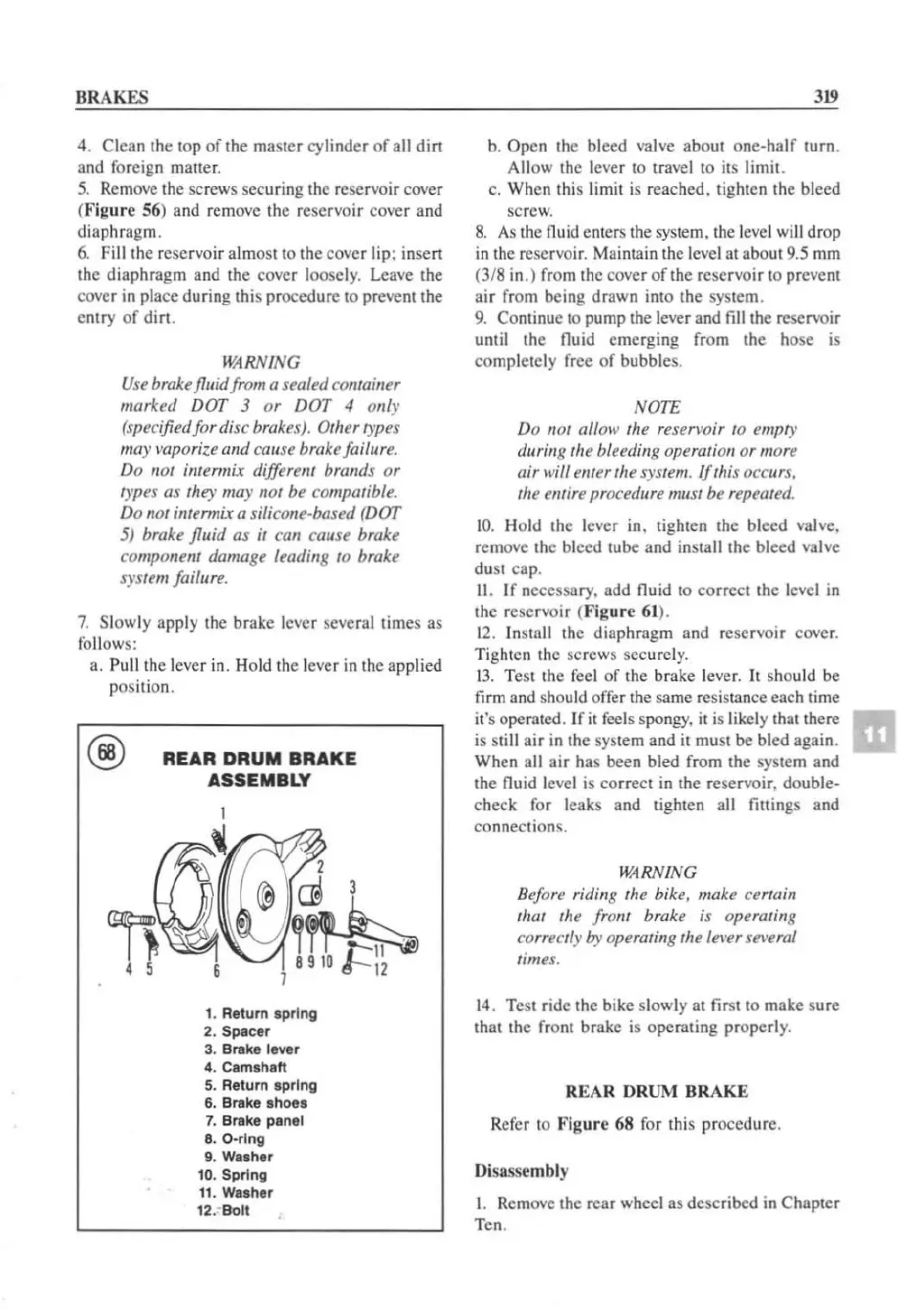
REAR
DRUM
BRAKE
ASSEMBLY
2
@ m 3
!~
6 7 &"-12
1. Return s
pring
2. Spscer
3. Brake lever
4. Camshaft
5. Return s
pr
ing
6.
Brake sh
oes
7.
Brake psnel
8. O·rlng
9. Washer
10
. Spring
11
. Washer
12
.-
8011
319
b.
Opcn the bleed val
ve
about one-half
(Urn.
Allow the lever to travel to its limit.
c.
When this limit is reached. tighten the bleed
sc
r
ew.
8.
As
the fluid e
nl
ers the system,
th
e
lev
el will drop
in
the reservoir. Maintain the level al aboU19.5 mm
(3/8
in.) from the cover
of
the reservoir to prevent
air
from being drawn into the system.
9.
Continue to pump
th
e lever and fill the reservoir
until the fluid emerging from the hose is
completely free
of
bubbles.
NOTE
Do
1101
affoll' tile reserl'Oir
to
empty
durillg tile bleedillg operation
or
more
air
will emer the system. If this occurs,
tile emire
procedure mllst be repeated.
1
0.
Ho
ld
the lever in. tighten the bleed valve.
remove the bleed tube and install the bleed
va
l
ve
dust cap.
11
. If necessary. add fluid to correct the level
in
the reservoir (
Figure
61
).
1
2.
Insta
ll
the diaphragm and reservoir cover.
Tighten the screws securel
y.
13.
Test the feel of the brake lever. It should be
firm and should offer the same resistance each time
it's operated.
Ifit
feels spongy.
it
is
likely that there
is
still air
in
the system and il must
be
bled again.
When all air has been bled from the system and
the fluid level
is
correct in the reservoir, double-
check for leaks and tighten all fillings and
co
nn
ections.
WARN
ING
Bef
ore riding the bike, make
cer
tain
that the
from
brake is operating
correctly
by operating the lel'er Sel'erai
times.
14.
Test ride the bike slowly at first to make sure
that the front brakc
is
operating properly.
REAR
DRUM
BRAKE
Refer to Figure
68
for this proccdure.
Di
sassembly
1.
Removc the r
car
wheel as dcscribed
in
Chapter
Ten.
 Loading...


