48
Automatic Decompression Cable Adjustment
Adjust the automatic decompression cable at the
inter
val
indicated
in
Table 2. If the engine is dif-
ficult to Slart, the automat
ic
decompression cable
probably needs adjusting.
I. Remove the seal as described under Seat
Remoml//nsrafilllion
in
Chapter Twelve.
2.
Remove the
fue
l lank as described under File!
Ttlllk Remol'll
l/
lnSllllfarioll
in
Chapter Seven.
3.
Remove the bolt and cap nut securing the
cy
l-
inder head left-hand cover (Figure 63). Remove
the
cove
r
and
rubber cushions.
4. Carefully disconnect the spa
rk
plug lead (Fig-
ur
e 64) from the spark plug.
tfi5\
5.
Remove the spa
rk
plug from
th
e cylinder head.
~
NOTE
Either
lise
II
wide
jloHipped
scr
ell'dril'er
or
a specia/lOo{ made
by
Honda.
n,is
special tool (Figure 65)
(Homla part
No.
07700-00100(1) is
/IImle
specifically/or this purpose
and
if
caref
ully used,
wi/J
1101
mar
or
dam-
age the surface on the inspection
cOI'er.
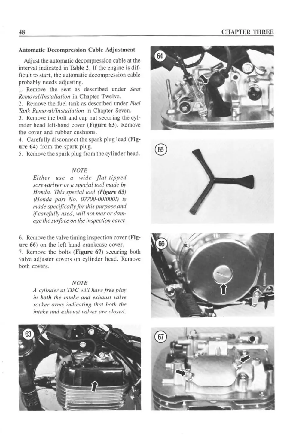
6.
Remove the valve timing inspection cover (Fig-
ur
e 66) on the left-hand crankcase cover.
7.
Remove the bolts (
Figur
e 67) securing both
valve adjuster covers
on
cy
linder head.
Rem
ove
both covers.
NOTE
A l.)·limJer at
IDC
will
hOl'e
free play
ill
both the imake alld exhaust \'a/I'e
rocker arms indicating thm both the
intake and exhaust \'a/l'es are closed.
CHAPTER
THREE
 Loading...


