302
5.
Tie the loose end
of
the hose
up
to
the
handlebar. Place the hose end
in
a rcsealable plastic
bag
and
zip
the
bag
closed around
the
hose
to
prevent the entry
of
moisture and foreign maner.
6.
Rem
ove
the trim plug (8. Figure 9) from each
clamp boll.
7.
Remove the clampi
ng
bolls (t"ig
ur
e
II
) and
clamp
securi
ng
the master cylinder to the
handlebar and remove the master
cy
linder.
8.
Insta
ll
by reversing these removal steps. Note
the following during installation.
9.
I
nSla
ll
the
clamp
with the rear view mirror
receptacle facing
up
. Align the face
of
the clamp
with the punch mark on the handlebar. Tighten the
upper
bolt
fi
rst. then the lower to the torque
specifica
ti
on listed
in
Table
I.
10.
Place a sealing washer on each side
of
the
brake hose fining and
in
stall the union bolt .
11
.
Tightcn
thc
union
bolt
to thc
torquc
specification listcd
in
Table
I.
12.
Blccd the front brakes as described under
Bleeding the System in Ihis chapler.
Disasse
mbly
Refer
10
Figure
U for models wilh slraight
handlebars
or
Figur
e
13
fo
r models wilh pulled
back handlebars for this procedure. The only
difference belween the 2 models is the location
of
the union bolt hole in the reservoir.
I. Remove the mastcr cylinder as described in Ihis
chaplcr.
@
,
CHAPTER ELEVEN
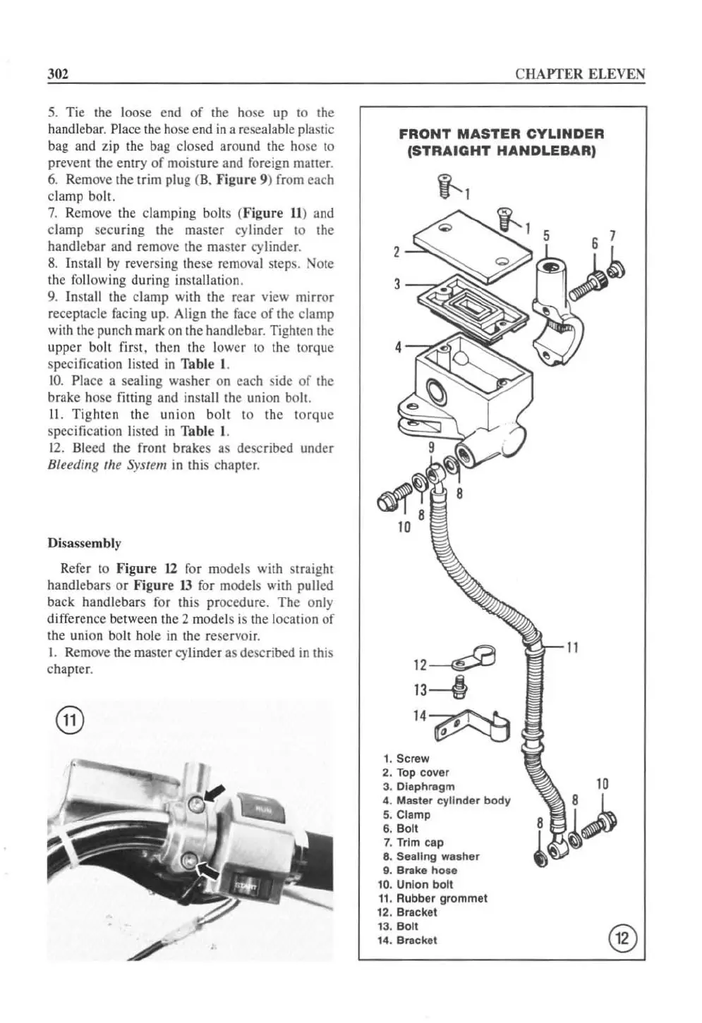
FRONT
MASTER
CYLINDER
(STRAIGHT
HANDLEBAR)
i-l
4
12~
13---1f
1. Screw
2.
Top
cover
3.
DIaphragm
4. Master cylinder body
S.
Clamp
6.
Bolt
7. Trim
cap
8. Sealing
Wisher
9. Bra
ke
hO
le
10. Un
io
n bo
lt
11
. Rubber grommet
12.
Bracket
13. Bo
lt
14
. Brack
el
®
 Loading...


