246
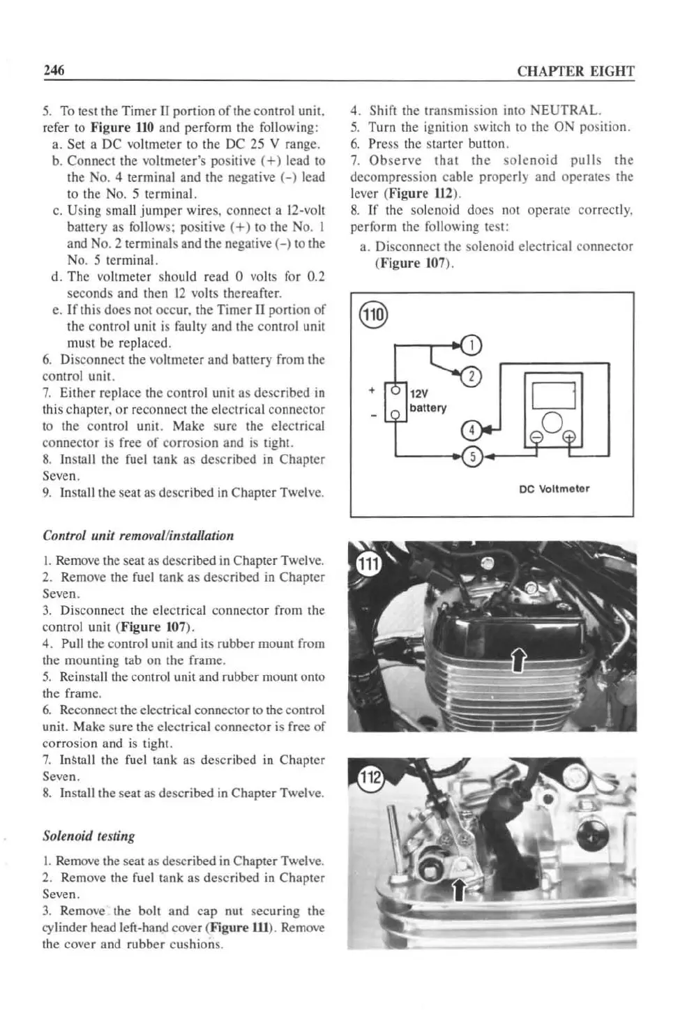
5.
To
te
St
the Timer
II
porlioo
of
the contr
ol
unit.
refer to
Figure
110
and perform the following:
a.
SCI a DC voltmeter to the DC 25 V range.
b.
Connecllhe
vo
ltmeter's positive
(+)
lead
to
the
No.4
terminal and the negative
(-)
lead
to the
No.5
terminal.
c. Using small
jumper
wi res. connect a 12-voll
battery as follows: positive
(+)
to the No. 1
and N
o.2
terminals and the negative
(-)
to the
No.5
terminal.
d. The voltmeter should
read
0 voils for 0
.2
seconds and
th
en 12 volts
th
ereafter.
c.
Irthi
s does not occ
ur
. the Timer
II
portion of
the
co
ntrol unit is faulty
and
the
co
ntrol unit
mu
st be replaced.
6.
Di
sconnec
llh
e
vo
hmCl
er and battery from the
control unit.
7.
Either replace the control unit as described
in
this chapter.
or
reconnect the electrical co
nn
ect
or
to the
co
ntrol unit . Make sure the electrical
conne
ctor
is
free
of
co
rrosion and
is
tight.
8.
Ins
IBII
the
fu
el tank as described
in
Chapt
er
Seven.
9.
Install the scat as desc
ri
bed
in
Chapter Twel
ve
.
Control IInit
remo~'al/ins
talla/i
on
I.
Remove the seat as described
in
Chapter Twel
ve.
2. Remove the
fu
el tank as described
in
Chapter
Seven.
3.
Di
sconnect the ele
ct
rical
co
nnec
tor
from
th
e
control unit (
Figure
107).
4. Pull
th
e control unit and its rubber mount from
the mounting tab on the frame.
S.
Reinsta
ll
the control unit and rubber mount o
nt
o
th
e frame.
6.
Reconnect the electrical connector to the control
unit. Make s
ur
e the electrical co
nn
ector is free
of
corrosion and
is
ti
ght.
7.
InStall the fuel tank as described
in
Chapter
Seven.
8.
Insta
ll
the seat as desc
ri
bed
in
Chapter Twel
ve.
Solenoid testing
I. Remove the seat as described
in
Chapter Twel
ve.
2. Remove the fuel tank as described
in
Chapter
Seven.
3.
Remove the boll and cap nut securing the
cy
linder head left-hand cover (
figure
ill
). Remove
the cover and rubber cushions.
CHAPTER
EIGHT
4. Shift the transmission into
NEUTRAL.
S.
Turn the ignition switch to the ON position.
6.
Press the start
er
button.
7.
Observe
thaI
the
so
l
enoid
pulls
the
decompression cable properly and operates the
le
ver (
Figur
e
112
).
8.
If the solenoid does not operate correctly.
pe
rf
orm
the following test:
a. Disconnect the solenoid electrical connector
(
Figure
107
).
+
12V
battery
DC
Voltmeter
 Loading...


