LUBRICATION,
MA
INTENANCE AND TUNE-UP
51
CAUTION
In
the next slep, do
'101
direct
compressed air toward
Ihe
ou
ts
ide
(opposite
th
e carbureior side) surface
of
Ihe
element.
If
air pressllre is
direcled
10
Ihe
outside surface it will
for
ce
lh
e
din
and
dllSI
into the pores
oflhe
elemem tlms restricting airflow.
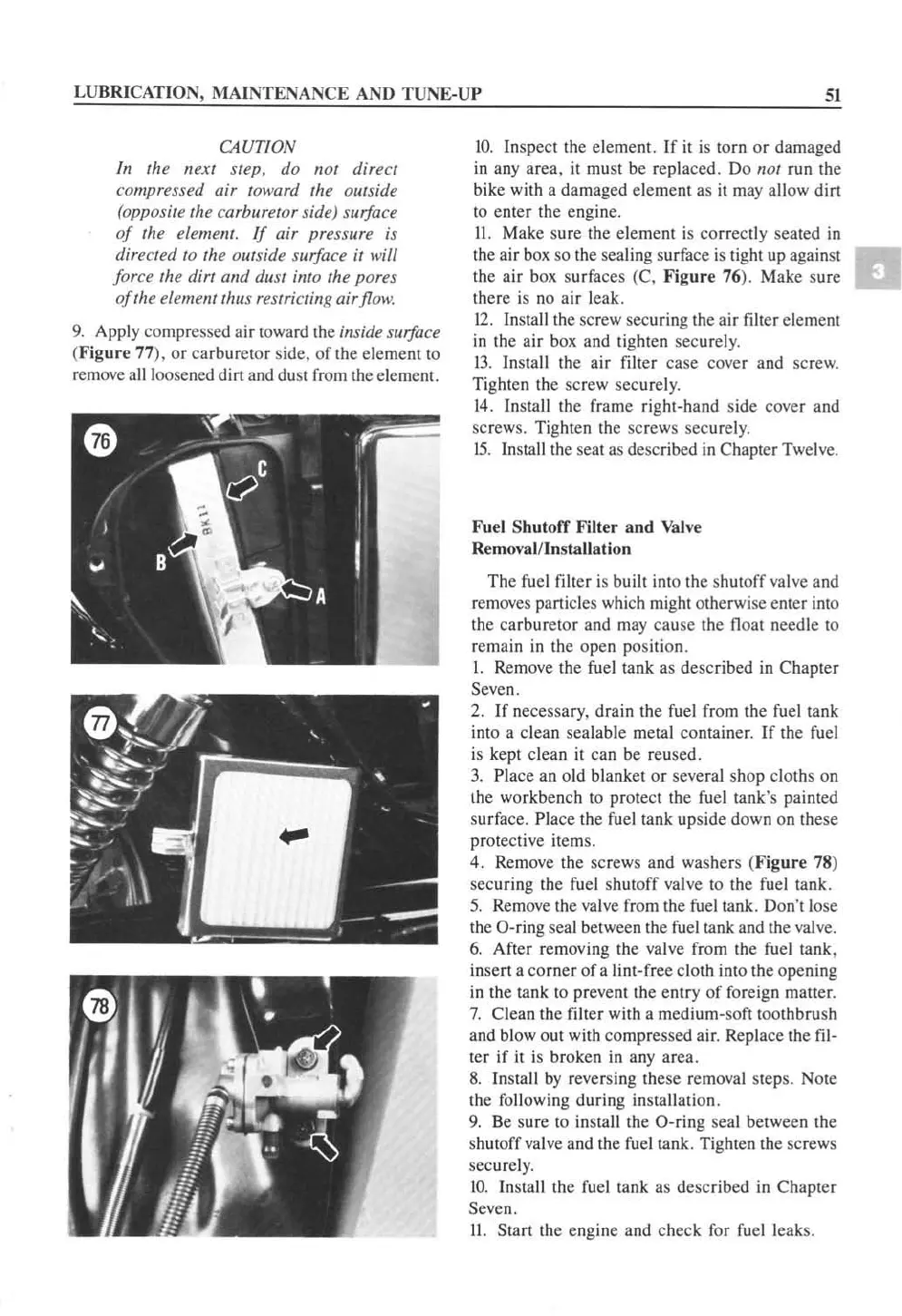
9.
Apply compressed
ai
r toward
th
e inside surface
(Fig
ur
e 77),
or
carburetor side,
of
th
e eleme
nt
to
remove
all loosened dirt a
nd
dust from the eleme
n!.
10.
Inspect the clement. If
it
is
torn or damaged
in any area,
it
mu
st be replaced. Do 1101 run the
bike with a damaged eleme
nt
as
it
m
ay
allow dirt
to
enter the engine.
II.
Make sure the element is correctly seated in
the air
b
ox
so
the seal
ing
surface
is
tight up against
the air
box
surfaces (C. Figure 76). Make
su
re
there is no air leak.
12
. Ins
tall
the
sc
rew
securing the air filter eleme
nt
in
the
ai
r
box
and tighten securel
y.
13
. Install the air filter case cover and scre
w.
Ti
ghten the sc rew securel
y.
14.
In
stall the frame right-hand side cover and
screws. Tighten the sc rews securel
y.
15
.
In
s
tall
the seat
as
described
in
Chapter Twel
ve.
Fuel Shutoff Filt
er
and
Va
l
ve
Removal/Insta
ll
ation
The fuel filter is built into
th
e shutoff valve and
rem
oves
particles which might otherwise e
nt
er into
the carburet
or
and
ma
y cause the float needle
to
remain in the open position.
I. Remove the fuel tank
as
described in Chapt
er
Seven.
2.
If necessary, drain the
fuel
from the fuel tank
into a clean sealable metal container.
If
the
fuel
is kept clean
it
can
be
reused.
3.
Place an old blanket
or
seve
ra
l shop cloths on
the workbench
to
protect the
fue
l tank's painted
surface.
Place the
fu
el tank up
si
de down on these
protective ite
ms.
4. Re
mov
e the screws and washers (Figure
78
)
securing the fuel shutoff
va
lve
to
th
e fuel tank.
5.
Remov
e the valve from
th
e
fue
l tank. Don't lose
the O-ring seal between the
fuel
tank and the
va
l
ve.
6.
After rem
ov
ing the valve fr
om
the fuel tank,
insert a corner
of
a lint-free cloth into the opening
in
th
e tank to prevent the e
nt
ry of foreign matter.
7.
Clean
th
e
fi
lter with a medium-so
ft
to
othbrush
and blowout wi
th
compressed air.
Rep
lace the fil-
te
r if
it
is broken in
any
area.
8.
In
stall by reversing these remo
val
step
s.
Note
the following
du
ring installation.
9.
Be sure to
in
stall
th
e O-ring seal be
tw
een the
s
hu
toff
va
l
ve
and the
fuel
tank. Tighten the screws
securely.
10
. Install the
fu
el tank as described
in
Chapter
Seven.
II.
Start the eng
in
e and c
he
ck for
fuel
le
ak
s.
 Loading...


