46
NOTE
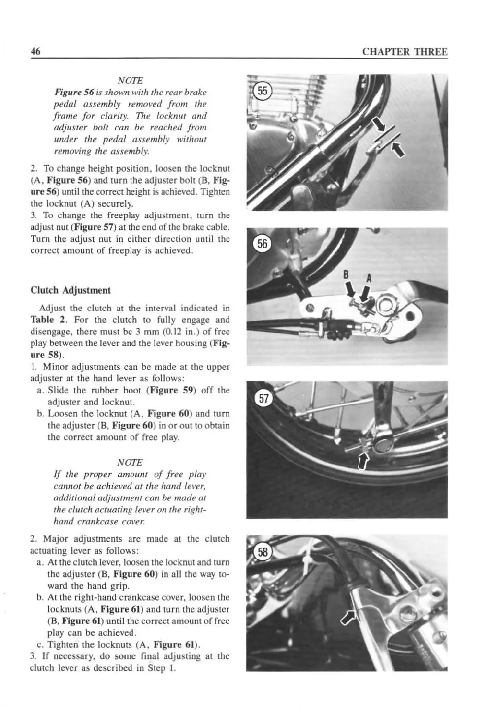
Figure 56 is shown with the rear brake
pedal assembly removed from the
frame for clarity.
11lt
locknut ami
adjuster bolt can be reached from
wuler
Ihe
pedal assembly
wilholl/
removing the assembly.
2.
To
change height position. loosen the locknut
(A.
Figure
56
) and
tUfn
the adjuster bolt (B.
Fig·
ur
e
56
) umil the
co
rrect heighl
is
achieved. Tighlen
the locknut (A) securely.
3.
To change the freeplay adjustment. turn the
adjust nut
(Fi
gure
51) at the end
oflhe
brake cable.
Turn
the adjust nut
in
either direction until the
correct amount
of
freepJay
is
achieved.
Clutch Adjustment
Adjust the clutch al the interval indicated
in
Table
2. For the clutch 10 fully engage and
disengage. there must
be
3 mm
(0.12
in.)
of
free
play between the lever and the
le
ver housing (Fig-
ur
e 58).
I. Minor adjustmenls can
be
made at the
upper
adjuster at the hand lever as follows:
a.
Slide the rubber
boO!
(Fi
gure
59)
of
f the
adjuster and locknut.
b.
Loosen the locknut (A.
Figure
60
) and turn
the adjuster
(B.
Figure
60)
in
or
out
to obtain
the
co
rrect amounl of free play.
NOTE
If
the proper amoum
of
free pia)'
callnot be achieved
at
the hand lel'er,
additional adjustment can be made
01
the clutch actuating le\'eronthe right-
halld crankcase
cover.
2. Major adjustments
are
made at the clutch
actuating lever as follows:
a.
At
the clutch lever. loosen the locknut and turn
the adjuster
(
8.
Fig
ur
e 60)
in
all the way to-
ward the hand grip.
b.
At
the
ri
ght-hand crankcase cover. loosen the
lock
nu
ts (A. F
igur
e 61) and turn the adjuster
(8 .
Figu
re 61) until
th
e
co
rrect amount
of
free
pl
ay
can be achieved.
c. Tighten the locknuts (A.
Figu
re 61).
3.
If necessary.
do
some final adjusting
at
the
clutch lever as described
in Step I.
CHAPT
ER
THREE
 Loading...


