11
6
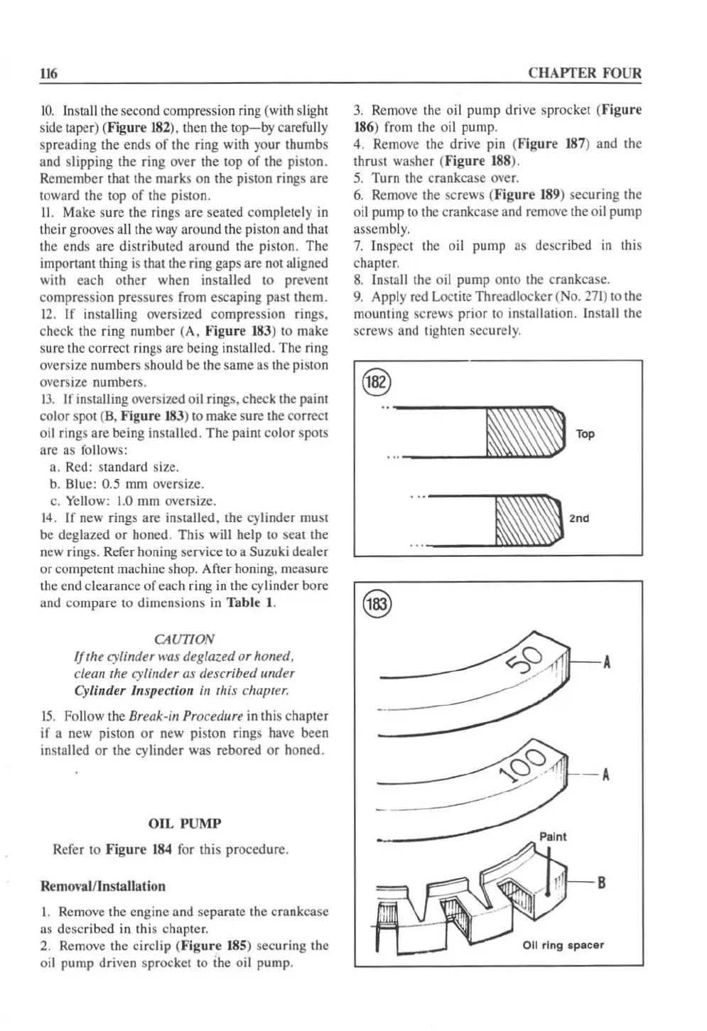
10.
Install the second compression ring (wi
th
sl
ig
ht
side taper) (Fig
ur
e
182
). then the
lOp-by
carefully
spreading the ends
of
the ring with your thumbs
and slipping the ring over the
lOp
of
the
pi
ston.
Remember that the marks on the piston rings
are
toward the top
of
the piston.
11.
Make sure the rings arc scated completely in
their grooves a
ll
the
way
around the pislon
and
that
the ends are distributed around the piston. The
imponant thing
is
thalthc
ring gaps afe not aligned
with each
other
when installed to prevent
compression pressures from escaping
pa
st them.
12
. tr installing oversized compression rings.
check the ring number (A,
fi
g
ur
e 183) to make
sure the correct
ri
ng
s arc being insta
ll
ed. The ring
oversize numbers should be the s
ame
as the piston
oversize number
s.
13.
I r installing oversized oil rings. check the paint
color spot (B. Figu
re
18
3) to make sure the correct
oil rings are being
in
stalled . The paint
co
lor spots
arc as
ro
ll
ows:
a. Red : standard size.
b. Blue:
0.5 mm oversize.
c. Yellow:
1.0
mm oversize.
14
.
If
new rings are installed, the cylinder must
be deglazed or honed. This will help to scat the
new ring
s.
Refer honing service to a Suzuki dealer
or competent machine shop. After honing. measure
the end clearance
of
each ring in the cylinder bore
and compare to dimensions
in
Table
1.
CAUTION
If
the cylinder was deglazed
or
honed.
clean the
cy
linder as described under
Cylinder Inspection
in
this chapter.
15.
Follow the Break
·i
ll
Procedure
in
this chapter
if
a new piston
or
new
pi
ston rings ha
ve
been
in
stalled
or
the
cy
linder was rebored
or
honed.
OI
L PU
MP
Rerer to Fig
ur
e
184
for this procedure.
Removal/Installa
ti
on
I. Remove the engine and separate the crankcase
as described in this chapter.
2. Remove the circlip (
Fi
g
ur
e
185
) securing the
oil pump driven sprocket to the oil pump.
CIIAPTER FOUR
3.
Remove the oil pump drive sprocket (Fig
ur
e
186) from the oil pump.
4. Remove the drive pin (Fig
ur
e
18
7) and the
thrust washer (Fig
ur
e 188).
5.
Turn the crankcase over.
6.
Remo
ve
the screws (Figu
re
1
89
) securing the
oil pump to the crankcase and
remove the oil pump
assembl
y.
7.
Inspect
th
e oil pump as described
in
this
chapter.
8.
Ins
ta
ll
th
e oil pump onto the crankcase.
9.
Apply red Loctite Thrcadlocker (No.
271)
to the
mounting
sc
rews
prior
to installation.
In
stall the
screws and tighten securel
y.
_ TOP
- A
B
 Loading...


