208
b. Loosen the bolt on the muffler clamp.
c.
Withdraw the
mume
r from the exhaust pipe.
d. In
spec
t the
connec
tor
on
the
exhaus
t
pipe
and
replace
if
necessary.
c. Assemble by reversing these
di
sassembly
sleps.
6.
In
stall a new gasket in the exhaust
pon
in
Ihccyl-
incleT
head.
7.
In
stall the exhaust system onlo the frame and
cn-
gme.
8.
Install the exhaust pipe clamp boils (on the
cy
l-
inder head)
on
ly finger-light un
til
Ihe
rest
oCthe
nuts
and washers arc installed.
9.
In
stall the nul
s,
washers and rubber cushions se-
curing the
mumer
to the
mumer
hanger.
Don',
for-
CHAPTER SEVEN
gel the spacer located within each rubber
cu
shion.
Tighten
Ihe nuts only finger-tight at this lime.
[0. Tighten the exhaust pipe clamp bolts to 18·28
N.
rn
(1)·
20
ft.-lb.),
NOTE
Tightellillg
Ihe
exhausl pipe boilS al
Ihe
cylinder heml Jirsl
I\
'ill
millill1i
=e
exhausl leaks tIIlhe
cy
li"d
er he
ad
.
II . Tighten the
tllumer
mounting nuts securely.
12.
After inSlallation is complete. start the engine
and make sure there are no
e;"haust leak
s.
13.
Remove the nuts and washers from the engine
fro
nt
mounting bolt
s.
14
. Install the front footpeg assembly and the
fr
ont
heat shield onto the engine mounting
boIl
S.
Tighten
the bolts to
70-80 N. m
(51
-
63
ft
.• lb.).
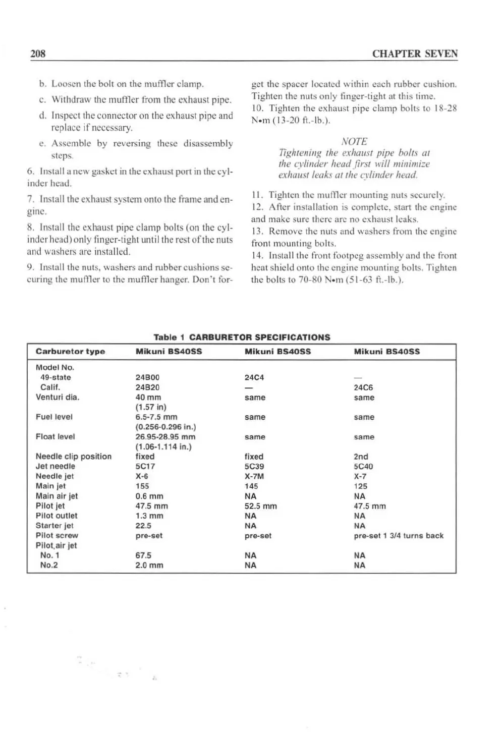
Ta
ble
1
CAR8URETOR
SPECIFICATIONS
Ca
rbur
e
tor
typ
e
Mlkunl
854055
Mikun
l
854055
Mikun
i
854055
Model No.
49-slale 24Boo 24C4
Calli.
24
820
24C6
Venturi
dia
.
40mm
same
same
(1.
57
In)
Fuel level
6.5-7.5
mm
same same
(0.256-0.296 In.)
Float level
26.95-28.
95
mm
same
s
ame
(1.
06-1
.114 In.)
Needle
clip
po
siti
on
fixed
fixed
",
Jet
needle
5CH
5C39
SC40
Needle
Jet
X"
X-7M
X-7
Main
Jet
155 145 125
Main air
lei
0.6 mm
NA NA
PllolJet
47.5
mm
52.5 mm 47.5 mm
Pilot
outlet
1.
3mm
NA NA
Starler
Jel
22.S
NA
NA
Pilot s
crew
pre-set
pre-set pre-set 1
31
4
turns
back
Pilol.alr
lei
No. 1 67.5
NA NA
No.2 2.
0mm
NA NA
 Loading...


