·2
5.
If
the drive belt exhibits any
of
these problems.
replace the
drive belt as described under Driw' Belt
R
emomll
/nsrallarion in Chapter Ten.
6.
Remove
the
wood block(
s)
from under the
c
ngine
.
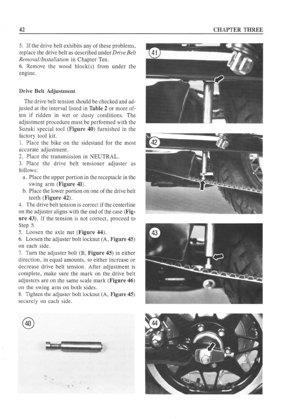
Drh
'e
Belt Adjustment
The drive beillension should be checked and ad-
justed
al
the interval listed in Table 2
or
more of-
Icn
if
ridden in wet
or
dusty conditions.
Th
e
adjustment procedure must
be
performed with the
Suzuki special too]
(F
igure
40) furnished in the
factory tool
kit.
I. Pla
ce
the bike on the sidcstand for the most
accurate
adjustment.
2. Pla
ce
the transmission
in
NEUTRAL.
3.
Place the drive belt lensioncr adjuster as
follows:
a.
Place the upper portion in the receptacle in the
swing arm (Figure
41
).
b.
Pl
ace the lower ponion on one
of
the drive bell
teeth (
Figure
42).
4. The dri
ve
belt tension is correct
if
the cente
rl
ine
on the adjuster aligns with the end
of
the case (Fig-
ur
e 43).
If
the tension
is
nOl
correct.
proceed to
Step
5.
5.
Loosen the axle nut (
Figur
e
44
).
6.
Loosen the adjuster bolt locknut (A,
Figure
45)
on each sidc.
7.
Turn the adjuster boll (8.
Figure
4
5)
in
either
direction.
in
equal amounts.
10
eit
her
increase
or
decrease
drive
belt tension. After adjuslment is
complete. make sure the mark on the
drive
bell
adjuslers
are
on the same scale mark (
Figure
46)
on the sw
in
g arm on both sides.
8.
Ti
ghten Ihe adjusler bolt locknut (A.
Figure
45)
securely on each side.
•
CHAPTER THREE
 Loading...


