ENGINE
31. Pla
ce
a copper washer between the clutch outer
housing and
th
e primary drive gea
r.
This will
prevent the p
ri
mary drive gear from rotat
in
g while
tightening the nut.
CAUTION
The primary drive gear nut has left-
hand
threads.
137
32. Turn the wrench counterclockwise and tighten
the
primary
drive
gear
nut to
the
torque
spec
ifi
cation listed
in
Table 2.
33.
Make sure the O-ring seal (Figure 268)
is
in
place
in
the engine pulley spacer. Apply a light coat
of
grease to the O-ring seal after
it
is
in
place. Slide
the
spacer
onlO the transmission mainshaft with
the O-ring side going
on
first.
34. Insta
ll
the oil control orifice (
Figure
243
) into
the right-hand crankca
se.
35.
Install the cylinder head cove
r,
camshaft.
cy
linder, piston. Slarter clutch assembly and
external gearshift
me
chanism as described
in
this
and
other
related chapters.
36. Install the speedometer drive shaft assembly
(Figure
240) into the crankcase. Tighten the bolt
(F
igure
239
) securely.
37.
In
stall the engine as described in this chapter.
38. Insta
ll
the starter motor and the alternator as
described
in
Ch
apter
Eight.
Crankcase
and
Crankshaft
Inspection
I. Remove the oil gallery plug and gasket (
Figure
269
) from the right+hand crankcase half.
2. Thoroughly clean the inside and outside
of
both
crankcase halves with cleaning solvent.
Dr
y with
compressed air. Make
sure
there is no solvent
residue left
in
the cases as it will contaminate the
new engine oil.
3.
Remove a
ll
old gasket sealing material from
both case half mating surfaces.
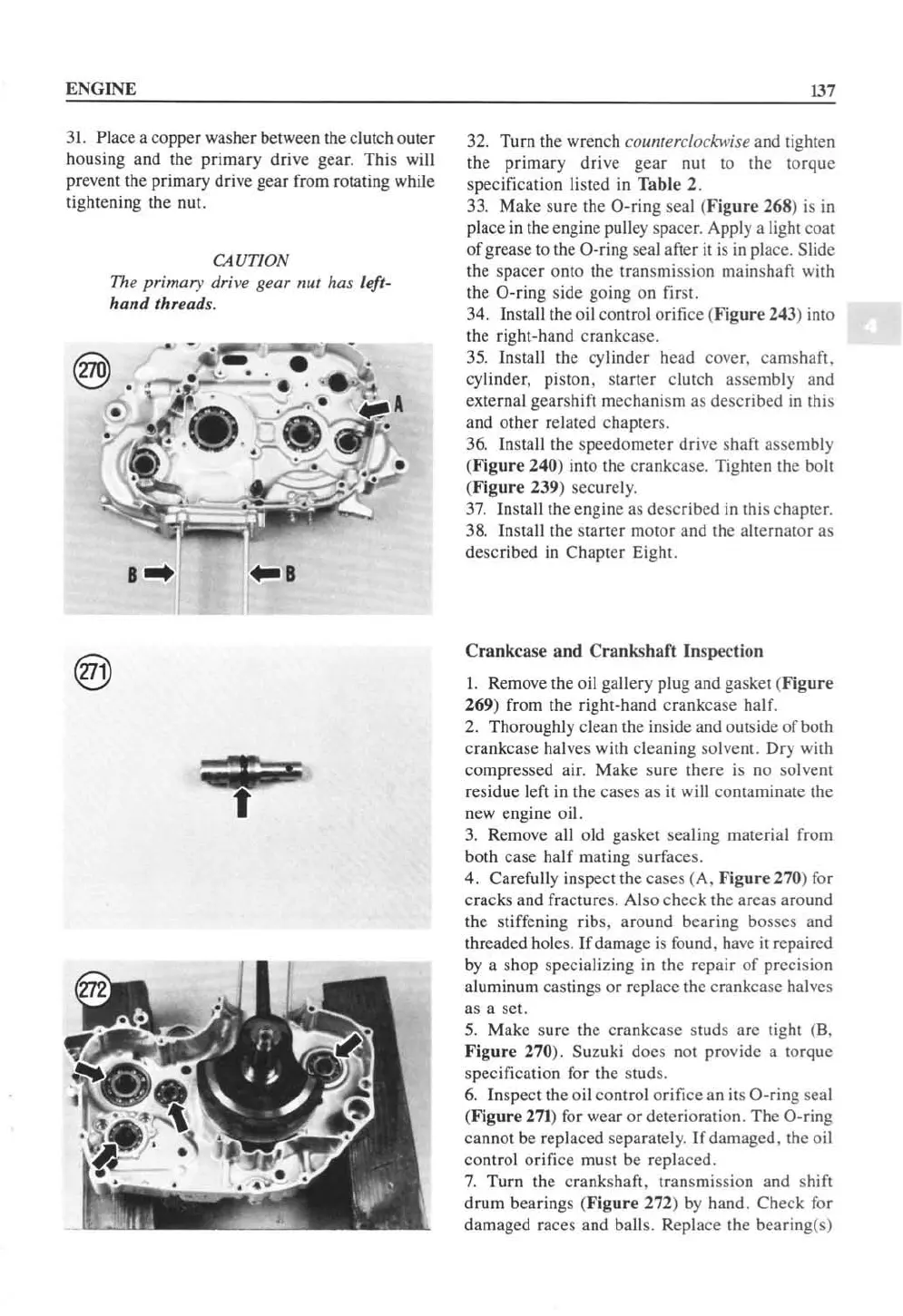
4. Carefully inspect the cases (A.
Figure
270) for
cracks and fractures. Also check the areas around
the s
tiff
en
in
g ribs. around bearing bosses and
threaded holes. If damage
is
found. have it repaired
by
a shop specia
li
zing
in
the repair of precision
aluminum castings
or
replace the crankcase halves
as a set.
5.
Make sure the crankcase studs are tight
(8.
Figure
270). Suzuki does not provide a torque
specification for the studs.
6.
Inspect the oil control
orifice
an its O-ring seal
(
Figure
271
) for wear
or
deterioration. The O-ring
ca
nn
ot
be replaced separately.
If
damaged. the oil
control orifice must be replaced.
7.
Turn the crankshaft, transmission and shift
drum bearings
(F
igure
272)
by
hand.
Check
for
damaged races and ball
s.
Repla
ce
the bearing(s)
 Loading...


