ENGINE
4.
Oi
l the piston pin and install
it
in
the connecting
rod. Slowly rotate the piston pin and check for
radial and axial play (
Figur
e
170
). If
any
play
exists. the piston pin should
be
replaced, providing
the rod bore is
in
good condition.
5.
Measure the
in
si
de diameter
of
the
pi
ston pin
bore with a snap gauge
or
caliper (Figure
171
) and
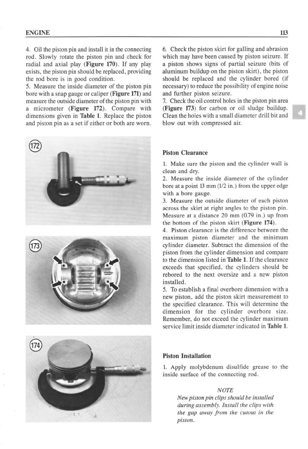
measure the outside diameter of the piston pin with
a micrometer (
Figure
172
). Compare with
dimensions given
in
Table
1.
Replace the piston
and
pi
ston pin
as
a set if either or both are worn.
• •
ill
6.
Check the piston skirt
for
galling and abrasion
which
may
have been caused
by
piston seizur
e.
If
a piston shows signs
of
partial se izure (bilS
of
aluminum buildup on the
pi
ston skirt). the piston
sh
ou
ld be replaced and the
cy
linder bored (if
necessary)
to
reduce the possibility of engine noise
and further piston seizure.
7.
Check the oil control
ho
l
es
in
the piston pin area
(F
igure
173
) for carbon
or
oil sludge buildup.
Clean the holes with a small diameter drill bit and
blowout
wi
th compressed air.
Piston Clearance
I. Make sure the piston and the cylinder wall is
clean and dry.
2.
Measure the inside diameter
of
the
cy
linder
bore at a point 13
mm
(112
in.) from the upper edge
with a bore gauge.
3.
Measure the outside diameter
of
ea
ch
pi
ston
ac
ross the skirt at right angles
to
the
pi
ston pin.
Measure at a
di
stance 20
mm
(0.79
in
.) up from
the bottom
of
the piston skirt
(F
igure
174
).
4.
Pi
ston clearance
is
the difference between the
maximum piston diameter and the minimum
cy
linder diameter. Subtract the dimension
of
the
piston from the
cy
linder dimension and compare
to
the dimension listed
in
Table I. If the clearance
exceeds that specified, the cylinders sh
ou
ld
be
rebored
to
the
next
oversize and a new
pi
ston
installed.
5.
To
establi
sh
a final overbore dimension with a
new piston. add the
pi
ston skirt measurement to
the specified clearance. This will determine the
dimension for the cylinder overbore size.
Remember, do not exceed the
cy
linder maximum
service limit inside diameter indicated in Table
I.
Piston Installation
I. Apply molybdenum
di
su
lfide grease
to
the
inside
su
rface
of
the connecting rod.
NOTE
New piston pin clips should be installed
durillg assembly.
hutoll
the clips with
the gap away from the
cutout ill the
piston.
 Loading...


