142
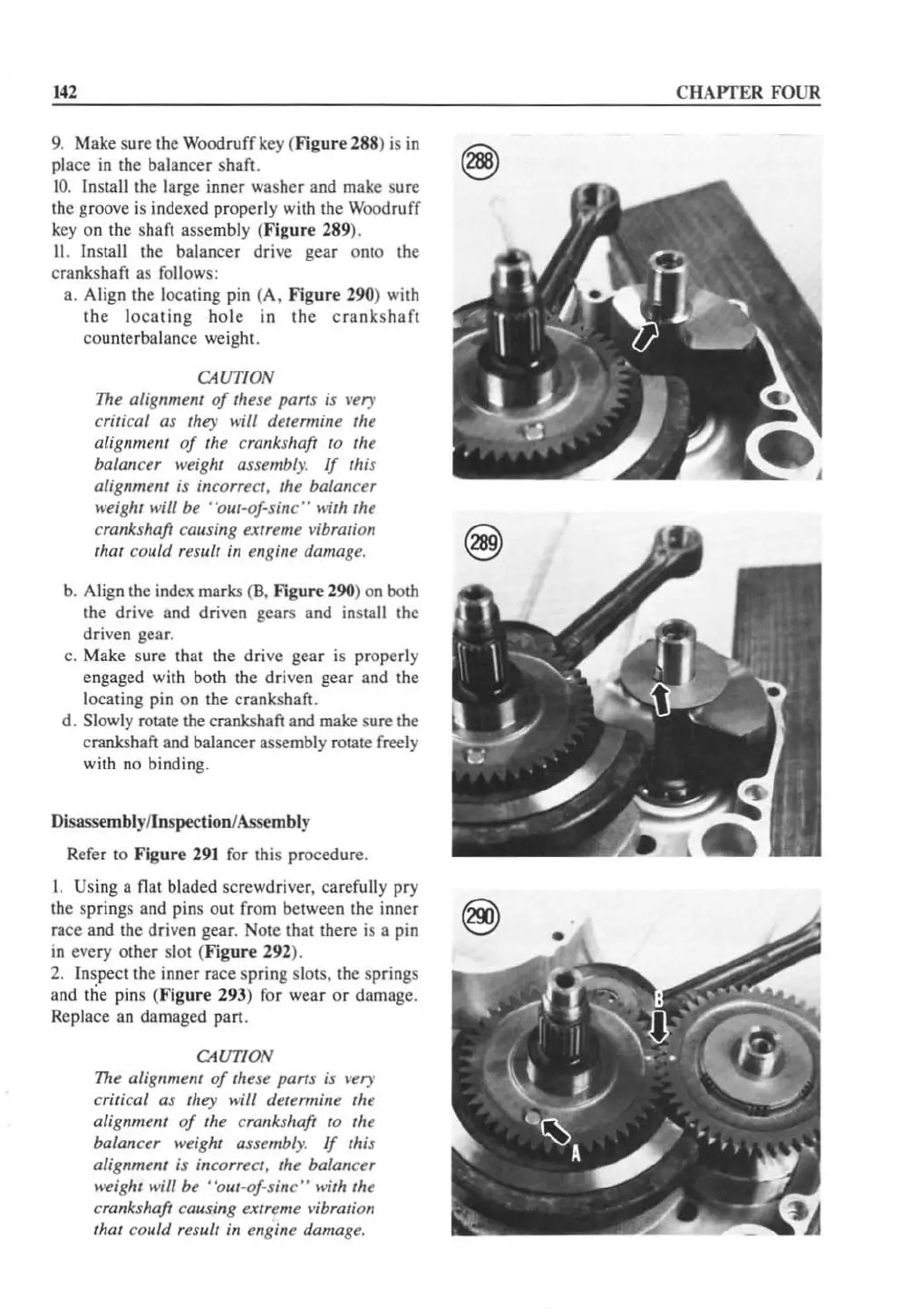
9.
Make sure the Woodruff
ke
y (
Figure
288) is in
pl
ace in the balancer shaft.
t
o.
Install the large inner washer and make s
ur
e
th
e groove is indexed properly with the Woodruff
ke
y on the shaft assembly (Figure 289
).
II
.
In
sta
ll
the balancer drive gear o
nt
o the
crankshaft as
fo
ll
ows:
a. Align the locating pin (A,
Figure
290) with
the
lo
cating
hole
in
the
c
rank
shaft
counterbalance weight.
CAUTION
The alignment
of
these parts is
W!ry
critical as they wiff determine the
alignmem
of
th
e crankshaft
to
th
e
balancer weight
assembly.
If
this
alignment is incorr
et
t, the balancer
weight
will be
"o
ut
-oJ-sine" with
th
e
crankshaft causing extreme
vi
bration
that co
ultJ
result in engine damage.
b. A
li
gn the index marks (8. Figure 290) on both
the drive and driven gears and install the
driven gear.
c. Make sure that the dri
ve
gear is prope
rl
y
engaged with both the driven gear and the
locating pin on the crankshaft.
d. Slowly rotate the crankshaft a
nd
make sure the
crankshaft and balancer assembly rotate freely
with no binding.
Disassembly/Inspection/Assembly
Refer to
Figure
291 for th
is
proced
ur
e.
I. Using a flat bladed screwdriver, carefully pry
the springs and pins out
fr
om between the inner
t293'
race and the driven gear. Note that there
is
a pin
~
in every other slot (
Figure
292).
2. Inspect the inner race spring slots, the springs
and the pins (
Figure
293) f
or
wear
or
damage.
Replace an damaged
pan
.
CAUT
I
ON
Th
e alignment
of
th
ese
pan
s is very
critic
al
as
th
ey wilf determine the
alignmenl
of
the crallkshaft to
th
e
balancer weight assembl
y.
If
this
alignment is
incorrect, the balancer
weight
will be
"o
ut
-oJ-sin
c"
with
th
e
crankshaft causing extreme vibration
that could
result in e
ll
gine damage.
CHAPTER
FOUR
 Loading...


