106
8.
If
the
CO
nla
et
area is too low on Ihe
va
lve.
or
100
narrow
, u
se
the 45° cutter and remove a
ponio
n
of
the lower area
of
lhe
va
l
ve
seal material to raise
and widen
th
e contact area (
Figure
148
).
9.
After the desired
va
l
ve
seat position and width
is obtained, use the
45° side of the cutter and
T-
ha
ndl
e and very
li
ghtly clean
off
any burrs
th
ai
may
have been caused
by
the previous cuts.
CAUTION
Do
not
use
any va
lve
lapping
compound after the final cut has
bun
made,
1
0.
Ch
ec
k that
th
e finish h
as
a smooth and velvety
s
urf
ace. It sh
ou
ld
not be sh
iny
or highly polished.
The final seating will take place when the engine
is first run.
11
. Repeal
SICPS
1-
10
fo
r
all
rema
in
ing
va
l
ve
se
al
s.
12.
Thoroughly clean the cylinder head and a
ll
va
l
ve
components
in
sa
lven! or detergent and hot
water.
13
.
In
stall the
va
l
ve
assembl
ie
s as described
in
this
chapter and fill the ports with solvent to check
fo
r
leaks.
If
any leaks are present, the valve seats must
be
inspected for
fo
reign matter or burrs that may
be preventing a proper seal.
14
. If the cylind
er
head and valve components
were cleaned in detergent a
nd
hot water, apply a
light
coal
of
engine oil to a
ll
bare metal surfaces
to preve
nt
any
ru
st formations.
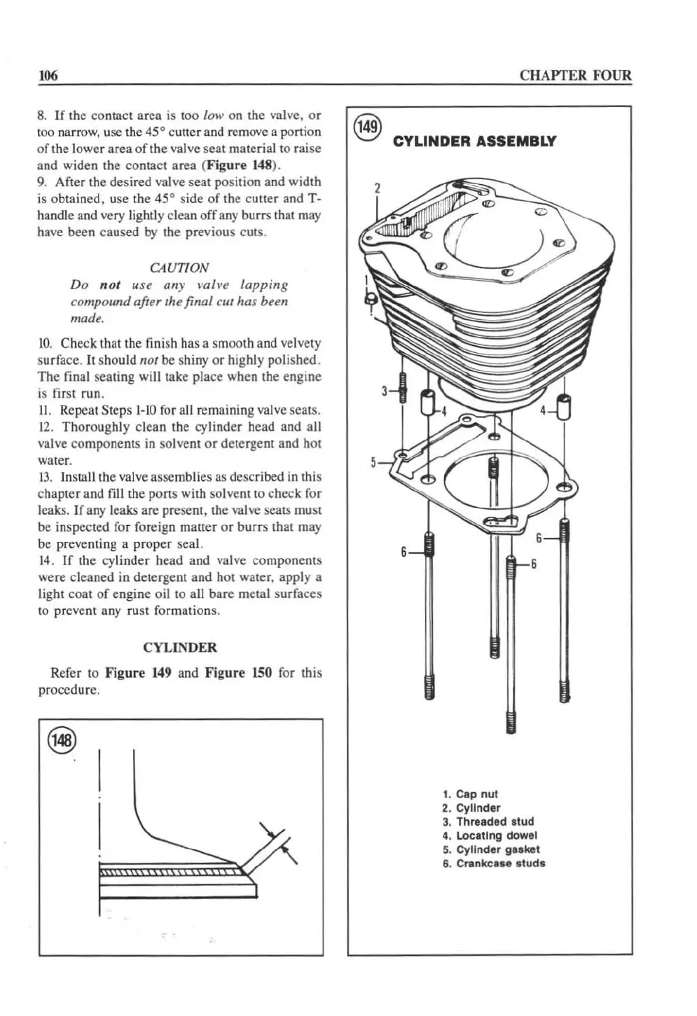
CYLINDER
Refer to
Figure
149
and
Figure
150
for this
procedure.
CHAPTER FOUR
r,4g\
\!:;!I
CYLINDER
ASSEMBLY
1. Cap nut
2.
Cylinder
3.
Threlded
stud
4. Locltlng dowel
5.
Cylinder
gllket
6.
Crankclle
studs
 Loading...


