128
13.
InSlall he drive bell
upper
cover a
nd
insta
ll
the
bo
lt (J' igu
re
220) securing the drive
be
lt upper
cover
at
the rear.
Ti
ghten the bolt securely (
Figure
235).
14
.
In
sta
ll
the lower cover (
B,
Figure
219).
15.
In
stall the bolt and washer (A. Fig
ur
e 219)
securing the front
of
both the drive bell upper and
lower covers at
th
e front.
16
. Install the bolt (
Figure
218) securing
Ih
cdri\'c
belt lower cover at the
rear
and tighten securel
y.
WARNI
NG
Be sure 10 secure the aitemlllor
electrical cable
and
emission control
hoses back to the frame
as
shown in
(
Figure
228).
lJth
e
electrical
cable
is
110/
sec
ur
ed
as
showll,
it will 11/0l
'e
ol'er
and
'he
dr;l't' bell wiff rub 0
11
it.
Th
e
dril't' belt will wear through the
insu[mioll and an elec
tr
ical shorl or
open
will
occur.
17.
In
s
la11
the lie wrap (
Figur
e 228) securing the
alterna
tor
electrical cable and emission contr
ol
hoses
10
the frame.
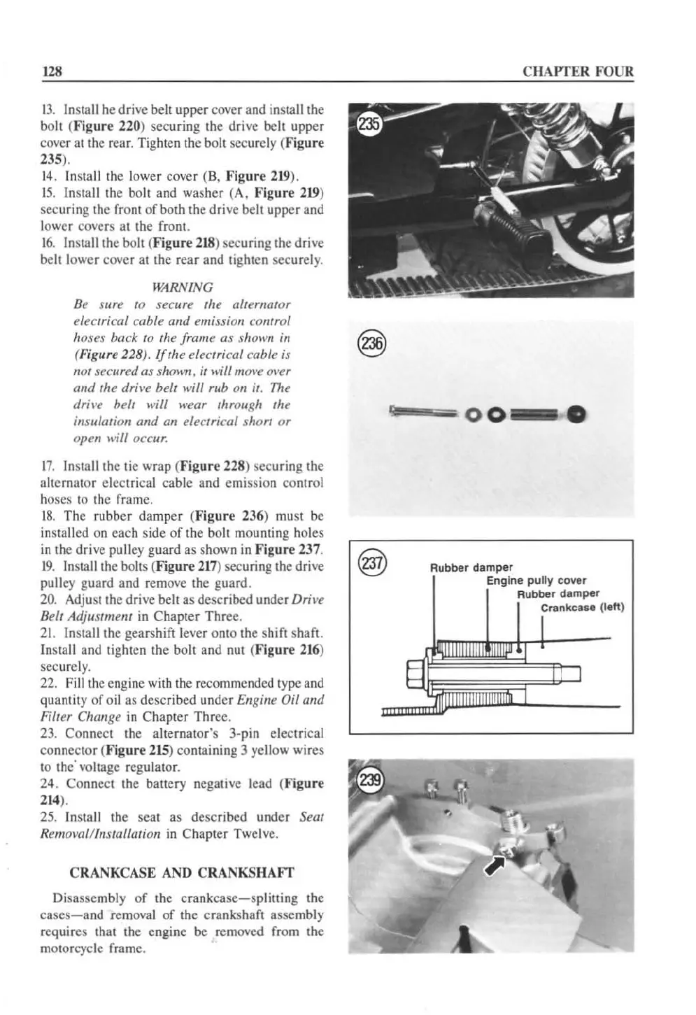
1
8.
The rubb
er
damper (
Figure
236) must be
installed on each side
of
the bolt mounting holes
in
the dri
ve
pulley guard as shown
in
Figure
237.
19
.
In
stall the bolts
(F
igur
e
217
) securing
th
e d
ri
ve
pulley guard and remove the guard.
20. Adjust the drive belt as described under
Dr
il'e
Bell Adjlwmem
in
Chapter
Thr
ee.
21.
In
stall the gearshift lever
on
to the shi
ft
shaft.
In
stall and tighten the bolt and nut (
Figure
216
)
securel
y.
22. Fill the eng
in
e with the recommended typc and
quantity of o
il
as described und
er
Ellgilie
Oil
alld
Filter Chan
ge
in
Ch
ap
t
er
Thre
e.
23. Connect the alternator
's
3·pin
electrical
connector (
Figure
215
)
co
ntaining 3 yell
ow
wires
to the
'vo
lt
age regulator.
24.
Co
nnect the battery negative lead (
Figure
2
14
).
25. Install the seat as described under Seal
Rem
ow
llilnstallation in Chapter Twel
ve.
CRANKCASE AND CRANKS
HAFT
Disassembly of the crank
case-s
plitting the
cases-a
nd
removal
of
th
e cranksha
ft
assembly
requires that the engine be removed from the
motorcycle frame.
C
HAPTER
FOUR
~~
-""
0
0--
•
damper
Eng
ine
pullV
cover
Rubber damper
C~""
...
(left)
 Loading...


