172
18
. Make su
re
the locating dowels (
Figur
e 35) are
in
place.
19.
In
stall a new gasket (
Fi
gure 36) and the eXler-
n[ll
gearshift mechanism cover.
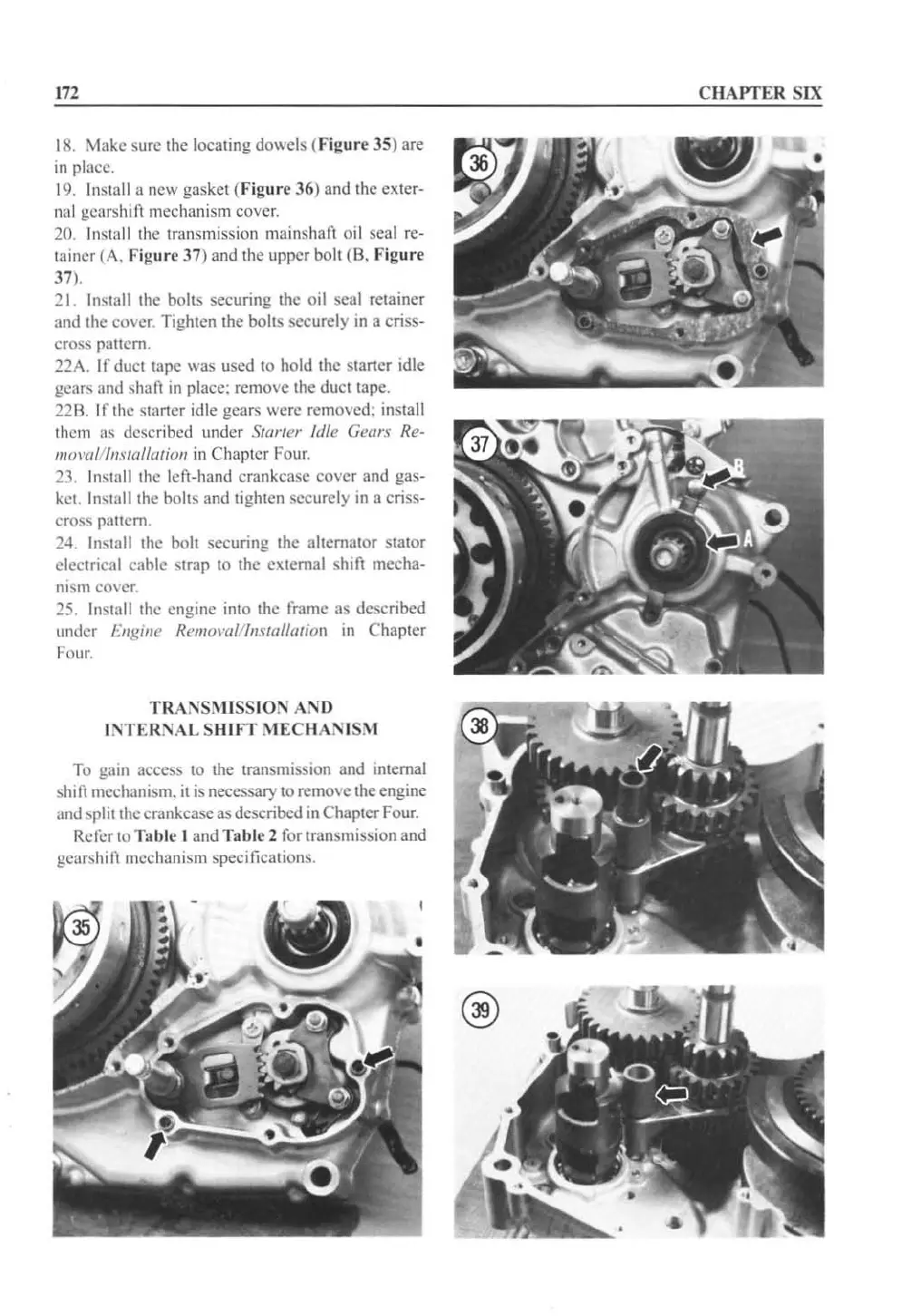
20. Install the transmission mainshaft o
il
seal re·
tainer (A. Figure 37) and the upper bolt (8. Fig
ur
e
37
).
21. Install the bolts securing the oil seal retainer
and the cover. Tighten the bolts securely
in
a criss-
cross pattem.
22A. If duct tapc was used to hold the starter idle
gears
and shaft
in
place: remove the duct tape.
220. If the starter idle gears were remove
d:
in
stall
them as de
sc
ribed under
SUlrIer
Idl
e Gears Re·
lIJol'{l/IJlIs/(III(lfioll
in
Chapter Four.
23,
In
stall the left-hand crankcase cover and gas-
ket.
In
sta
ll
the bollS and lighten securely
in
a criss-
cross
paltcm.
24. Install Ihe bolt securing the altemator stator
electrical cable strap to the extemal shift mecha-
nism
CO\
cr.
25.
Install the engine into the rrame as described
und
er
Engine Remomlllllstallation
in
Chapt
er
Four.
TRANSM
I
SSION
AND
I
NTERNAL
S
HIFT
MEC
li
ANI
SM
To gain access to the transmission and internal
shift mcehanism.
it
is necessary to remove the engine
and split the crankcase as described
in
Chapter Four.
Rererto
Tab
le I and Table 2 ror transmission and
gearshift mechanism specifications.
C
HAPTER
SIX
 Loading...


