ELECTRICAL SYSTEM
®
Battery
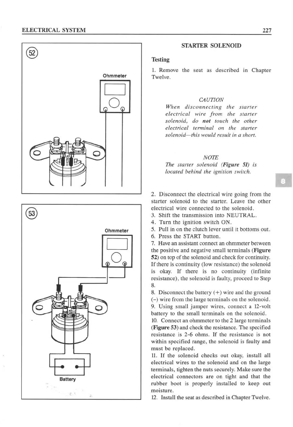
Ohmmeter
D
o
Ohmmeter
D
o
227
STARTER
SOLENOID
Testing
1.
Remove the seat as described in Chapter
Twelve.
CAUTION
W
hen
disconnecting
the
starter
electrical wire from the
starler
solelloid, do nol touch the arher
electrical termillal on the
starleT
solenoid-this
would result ill a short.
NOTE
The
slaner
solenoid (Figure
51
)
is
loea/ed behind the ignition n
...
·itch.
2.
Di
sconnect the electrical wire going from the
starter solenoid to the starte
r.
Leave the other
electrical wire co
nn
ected
to
the solenoid.
3.
Shift the transmission into NEUTRAL.
4.
Turn the ignition switch ON.
5.
Pull
in
on the clutch lever until
it
bottoms out.
6.
Pr
ess the START button.
7.
H
ave
an assista
nl
connect an ohmmeter between
the positive a
nd
negati
ve
s
malltcrminal
s (
Figure
52) on top
of
the solenoid and check for continuit
y.
If
there
is
continuity (low resistance) the solenoid
is okay.
If
th
ere
is
no continuity (infinite
resistance
).
lhe solenoid
is
faully. proceed to Step
8.
8.
Disconnect the ballery
(+)
wire and the ground
(
-)
wire from the large terminals on the soleno
id
.
9.
Using small
jumper
wires, connect a
12
-vo
ll
ballery to the small terminals on the soleno
id
.
10.
Connect an ohmmeter to the 2 large terminals
(Figure 53) and check
th
e resistance. The specified
resistance is 2-6 ohms.
If
the resistance is
nOI
wi
thin specified range, the solenoid is
fau
lty and
mu
st
be replaced.
II.
If
the solenoid checks out okay, install all
electrical wires
10
the solenoid and on the large
terminal
s,
tighten the n
ut
s securel
y.
Make sure the
electric
al
connectors are on tight and that the
rubb
er
boot
is
properly
in
stalled to keep out
moisture.
12.
In
sta
ll
the seat as desc
ri
bed
in
Chapter Twel
ve.
 Loading...


