234
wi
res. Also check
Ihe
bulb sockel for
corrosion; replace as necessary.
4.
Pu
sh
th
e lamp socket/electrical wire assembly
back into the housing. Make sure
it
is completely
scated to prevent the entry
of
water and moisture.
5.
Install the fuel lank as desc
ri
bed in Chapter
Twelve.
Ignition Switch
Continuity Test
SW
ITCH
ES
The ignition switch
ca
nnot
be
separated. If either
t
he
electrical or mechanical portions
of
l
he
switch
become defective.
th
e entire switch assembly must
be
replaced.
I. Remo
ve
the scat as described in Chapler
Twelve.
2.
Di
sconn
ecllhe
ignition switch 4-pin electrical
connector (
Figur
e
74
) con
ta
in
ing
4 wires
(I
red.
I orange. I
gray
and 1
brown),
3.
Usc
an
ohmmeter
and
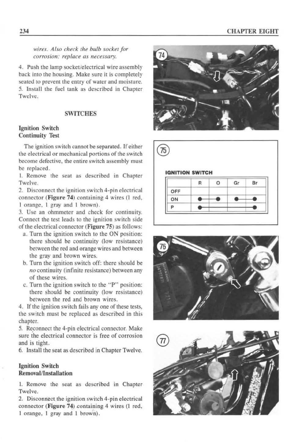
check for continuity.
Connect the test leads to the ignition switch side
of the electrical connector (
Figur
e 75) as
fo
ll
ows:
a.
Tu
rn the ignition switch to the ON position:
there should be continuity (low resistance)
between the red and orange wires and between
the gray and brown wires.
b.
Tu
rn the igni tion switch off: there should be
flO
co
ntinuity
(i
nfinite resistance) between any
of
these wires.
c.
Tu
rn the ignition switch to the
"P"
position:
there should be continuity (low resistance)
between the red
li
nd
br
own wire
s.
4. If the ignition switch
fai
ls
anyone
of
th
ese
te
sts.
the switch mu
st
be replaced as described
in
this
chapter.
5.
Re
,con
nC<:t
the 4-pin electrical co
nn
ector. Make
sure the electrical connector
is
free
of
co
rrosion
and is
ti
ght.
6.
Install the seat
liS
described in Chapt
er
Twel
ve.
Ignition Switch
Removallinstallal.ion
I. Remove the seat as described
in
Chapter
Twel
ve.
2. Disco
nn
ect the ignition
sw
it
ch 4-pin electrical
co
nn
ector (
Figure
74) containing 4
wi
res (I re
d.
I orange. I gr
ay
and I brown).
CHAPTER EIGHT
IQNITION
SWITCH
R 0
G,
B,
OFF
ON
P
®
 Loading...


