ELECTRICAL
SYSTEM
3.
Unhook the tie wrap and localc the starler
interlock switch's 2 individual yellow/green wires.
Disco
nn
ccll
hcse 2 individual electrical connectors
(."
igur
e
8J
).
4. Remove
the
screws securing the starter
interlock sw
it
ch
10
the clutch lever housing and
remove the switch assembly (
Figur
e
87
).
5.
Remove
th
e electrical wire harness from any
clips on the frame and
carefu
ll
y pull the harness
out from the frame.
6.
In
stall a new switch and tighten the screws
securely.
7.
R
econnect
the
2
individua
l
electrica
l
conncclOr
s.
8.
Make sure the electrical connectors arc free of
co
rrosion and arc tighl. Insta
ll
the tic wrap 10 hold
the electrical wi r
es
10
the
front
of
the frame. The
wires must be retained in this manner
10
allow
room
fo
r the fuel tank.
9.
In
slall
th
e f\lel tank as described
in
Chapler
Seven.
1
0.
In
sta
llihe
seat as described
in
Chapter
Tw
elve.
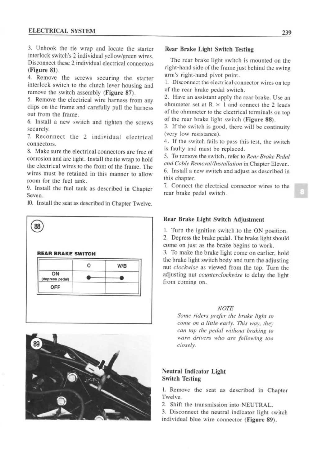
REAR
BRAKE
SWITCH
o
WI.
• •
239
Rear
Brak
e Light Switch Testing
The rear
bra
ke
light switch
is
mounted on the
right-hand side
of
the frame
JUSt
behind thc swing
arm's right-hand pivot point.
I. Disconnect the electrical connector wires on top
of
the rear brake pedal switch.
2. Have an assistant apply the r
ear
brake. Use an
ohmmeter
set
at
R x I and connect the 2 leads
of
the ohmmeter
10
the electrical terminals on top
of
the rear brake light switch (
Figure
88
).
3.
If the switch
is
good,
th
ere
will be continuity
(very low resistance).
4.
IC
the sw
it
ch fails to pass this test. the sw
it
ch
is
fau
lt
y and must be replaced.
5.
To remove the switch. refer
to
Rear Brake p
f'(Jal
mId Cable RemOI'(lll/lIsralllllion
in
Chaptcr Eleven.
6.
Install a new switch and adjust as described
in
this chapter.
7.
Connect the electrical connector wi r
es
10
the
rear brake pedal sw
it
ch.
Rear
Brak
e Light Switch Adjustment
t.
Turn the ignition switch to the
ON
position.
2.
Depress
th
e brake pedal. The brake light should
come on
JU
St
as [he brake begins to work.
3.
To make the brake light
come
on ea
rl
ier, ho
ld
the brake lig
ht
sw
it
ch body and turn the adjusting
nut
clockwiu
as viewed from the top.
Turn
the
adjusting nut
counterclockwise to delay the light
from coming on.
NOTE
Some rilJers prefer
fhe
brake light fO
come on a little
earl)"
711;s
lI'a)'.
Ihey
ClJn
tap fhe
pedal
lI'ithout braking to
lI'arn dril'ers who are following
tOO
closely.
Neutral
Indic
a
tor
Light
Switch Testing
1.
Remove the scat as described
in
Chapter
Twelve.
2.
Shift the transmission into
NEUT
RAL.
3.
Di
sco
nnect the neulTal indicator light switch
individual b
lu
e wire connector (
Figure
89
).
 Loading...


