Hydro:Evolved User Manual
October 2022 © 2022 Smartrise Engineering, Inc. All Rights Reserved Page 81
Bolt the 24” length of Unistrut to the two 18” lengths of Unistrut. See Figure 86.
NOTE: The 24” length may be bolted to the top of the two 18” lengths if applicable.
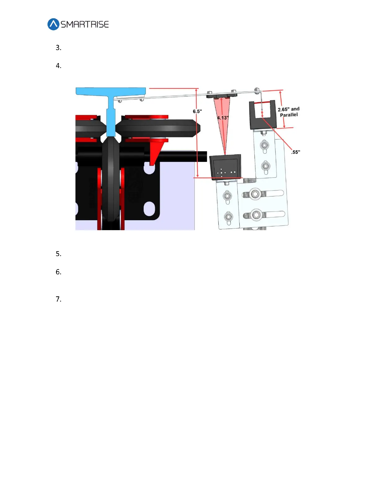
Temporarily affix a Tape Clip Assembly on the guide rail to use as an alignment for the
Sensor Array Assembly.
Figure 87: Sensor Array Assembly Positioning
Set the end of the 24” length Unistrut at 6.5” from the rear surface of the guide rail. See
Figure 87.
Loosely bolt the Sensor Array Assembly onto the 24” length of Unistrut with the Door
Zone Blade centered horizontally in the GLS Reader and parallel to the Tape Clip
Assembly. See Figure 87.
Position the Sensor Array Assembly according to the distances shown in then tighten all
bolts.
NOTE: The Optical Sensor Mount bolts may be loosened if needed to adjust the position
of the sensor.
After the Sensor Array Assembly positioning has been completed, the Sensor Array Assembly
needs to be fine-tuned for proper operation. See section 9.8 Fine Tune.
 Loading...

