Hydro:Evolved User Manual
October 2022 ©2022 Smartrise Engineering, Inc. All Rights Reserved Page 25
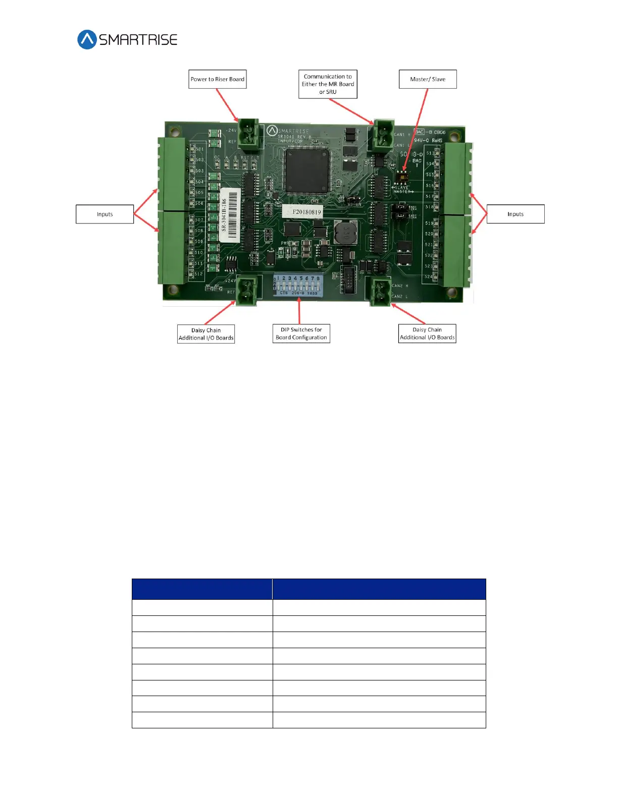
Figure 26: 24 Input Board SR3041
The serial communication is as follows:
• CAN1 – The Master board connects to the COP board’s AUX net.
• CAN2 – The Master board connects to CAN1 of the slave board.
NOTE: CAN2 of each slave board will be connected to CAN1 to the following slave board.
The assigned input for wiring is as follows:
• Inputs 501-508 – First address
• Inputs 509-516 – Second address
• Inputs 517-524 – Last address
The table below lists the 24 Input Board SR3041 DIP switch settings.
Table 7: 24 Input Board SR3041 DIP Switch Settings
 Loading...

