Hydro:Evolved User Manual
Page 20 © 2022 Smartrise Engineering, Inc. All Rights Reserved October 2022
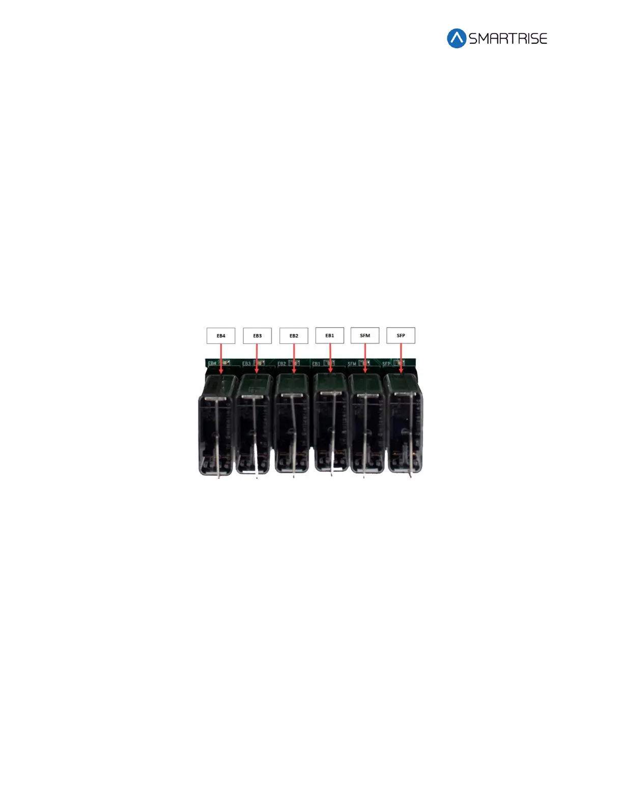
EB2 – The force guided relay that is controlled by the main processor. The status of the relay is
monitored by both the main processor and the safety processor. When the relay is active,
contacts that are in series with EB1 pass through voltage from the EBS terminal to the EB
terminal.
EB3 – The force guided relay that is controlled by the safety processor. The status of the relay is
monitored by both the main processor and the safety processor. When the relay is active,
contacts that are in series with EB3 pass through voltage from the EBS terminal to the EB
terminal.
EB4 – The force guided relay that is controlled by the main processor. The status of the relay is
monitored by both the main processor and the safety processor. When the relay is active,
contacts that are in series with EB1 pass through voltage from the EBS terminal to the EB
terminal.
NOTE: EB3 and EB4 are only used during preflight operation to bypass EB1 and EB2 relays so
they can be toggled without dropping the emergency brake.
Figure 23: MR Board SR3032 Safety Relays
2.2 CT/COP Board SR3030
The LEDs on the CT/COP board are either red, yellow, or green dependent upon the terminal
and status. Each color represents the following:
• Red – Indicates a fault has been detected or the board is resetting.
• Yellow – Indicates an active output terminal and alarm on the processors.
• Green – Shows power on an input terminal, power to the board and as a “heartbeat” to
show the software is running on the processors.
 Loading...

