Hydro:Evolved User Manual
October 2022 © 2022 Smartrise Engineering, Inc. All Rights Reserved Page 89
Connect the spring to the tape interlock bracket using the split ring. See Figure 98.
Adjust the spring tension by raising or lowering the Unistrut mounting point so that the
spring is stretched to approximately 3”.
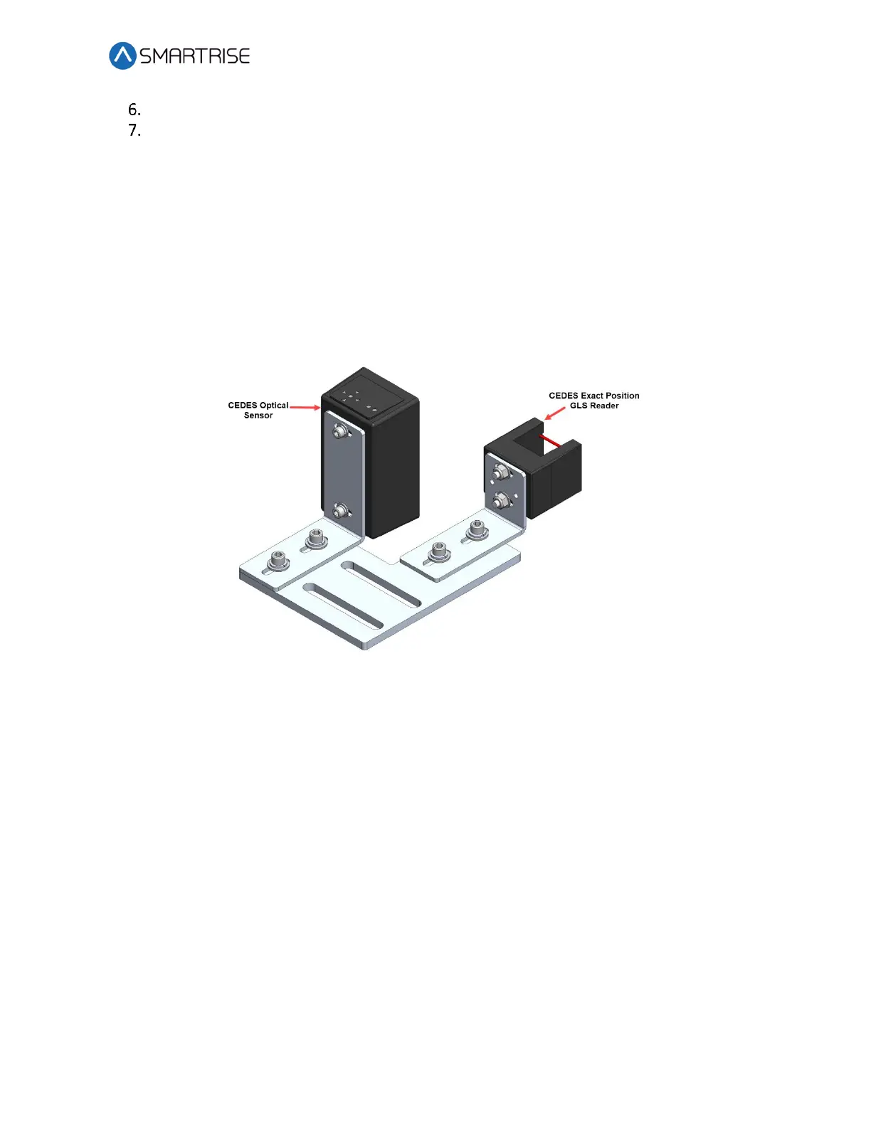
9.6 Sensor Array Assembly
The Sensor Array Assembly contains the CEDES Optical Sensor, CEDES Exact Position GLS
Reader, mounting brackets, and associated hardware. The sensors can be oriented differently
as long as the corresponding tape and blades are aligned correctly.
After assembly is complete, connect the CEDES Optical Sensor and the CEDES Exact Position GLS
Reader to the CT board and secure cabling.
Figure 100: Sensor Array Assembly
The Cedes Optical Sensor and Reader can be connected to either side of the sensor base plate
depending upon which side the Sensor Array Assembly is connected to the C-Channel. See
Figure 4 and Figure 5.
 Loading...

