Hydro:Evolved User Manual
Page 94 © 2022 Smartrise Engineering, Inc. All Rights Reserved October 2022
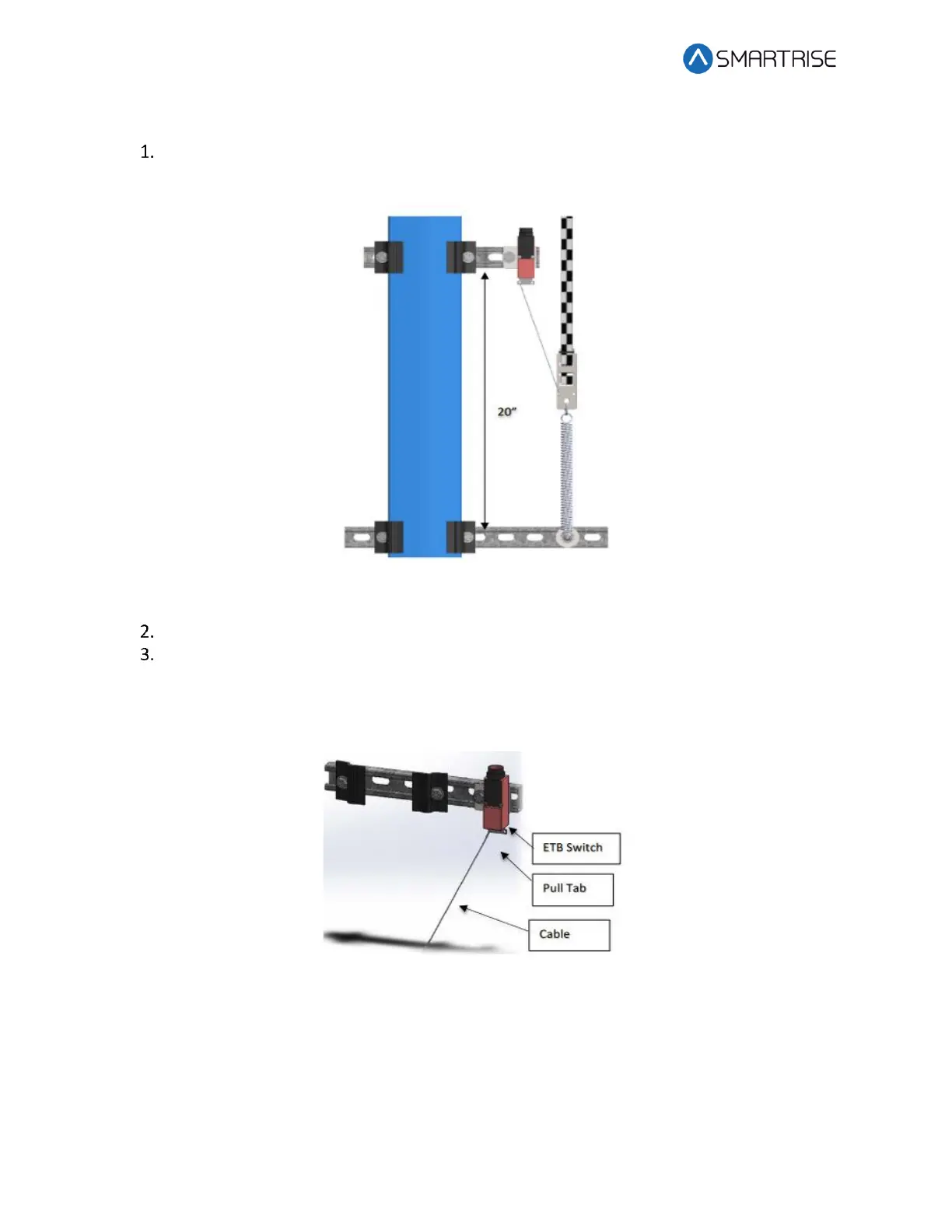
The following procedure describes how to install the ETB Switch Assembly.
Affix a 12” length of Unistrut to the bottom of the guide rail approximately 20” above
the Lower Tape Mount Assembly Unistrut.
Figure 107: Unistrut to Lower Tape Mount Assembly
Attach bracket and ETB switch to the Unistrut.
Link the ETB switch to the tape interlock via the cable kit provided. Leave 1-2“ for slack
in the cable.
NOTE: The switch can be mounted vertically as well as by inserting a switch pull tab into
the bottom end, pull should always face downward.
Figure 108: Emergency Tape Break Switch
9.8 Fine Tune
Prior to fine tune, verify the Sensor Array Assembly placement. The Sensor Array Assembly
should be at a distance of 4.13” with a tolerance of ±1 cm from the tape and parallel to the tape
clip mounting brackets. See Figure 87.
 Loading...

