Hydro:Evolved User Manual
October 2022 ©2022 Smartrise Engineering, Inc. All Rights Reserved Page 21
Each LED on the CT/COP board has a reference designator.
The input terminals are labeled 501 through 5XX (508 on the MR board). 24 VDC is connected
to the input terminals to run the logic circuitry.
WARNING
DO NOT APPLY AC CURRENT TO THE INPUT TERMINALS. APPLYING AC CURRENT WILL DAMAGE
THE BOARD.
The output terminal is connected to the negative side of the load and provides a reference
(REF) signal. The positive side of the load is connected to a 24 VDC power source.
If the yellow LED is not lit, the output transistors have no output and there is no load actuation.
WARNING
DO NOT APPLY 24 VDC DIRECTLY TO THE OUPUT TERMINAL WITHOUT A CURRENT LIMITING
DEVICE. THIS WILL CAUSE DAMAGE TO THE OUTPUT TRANSISTORS.
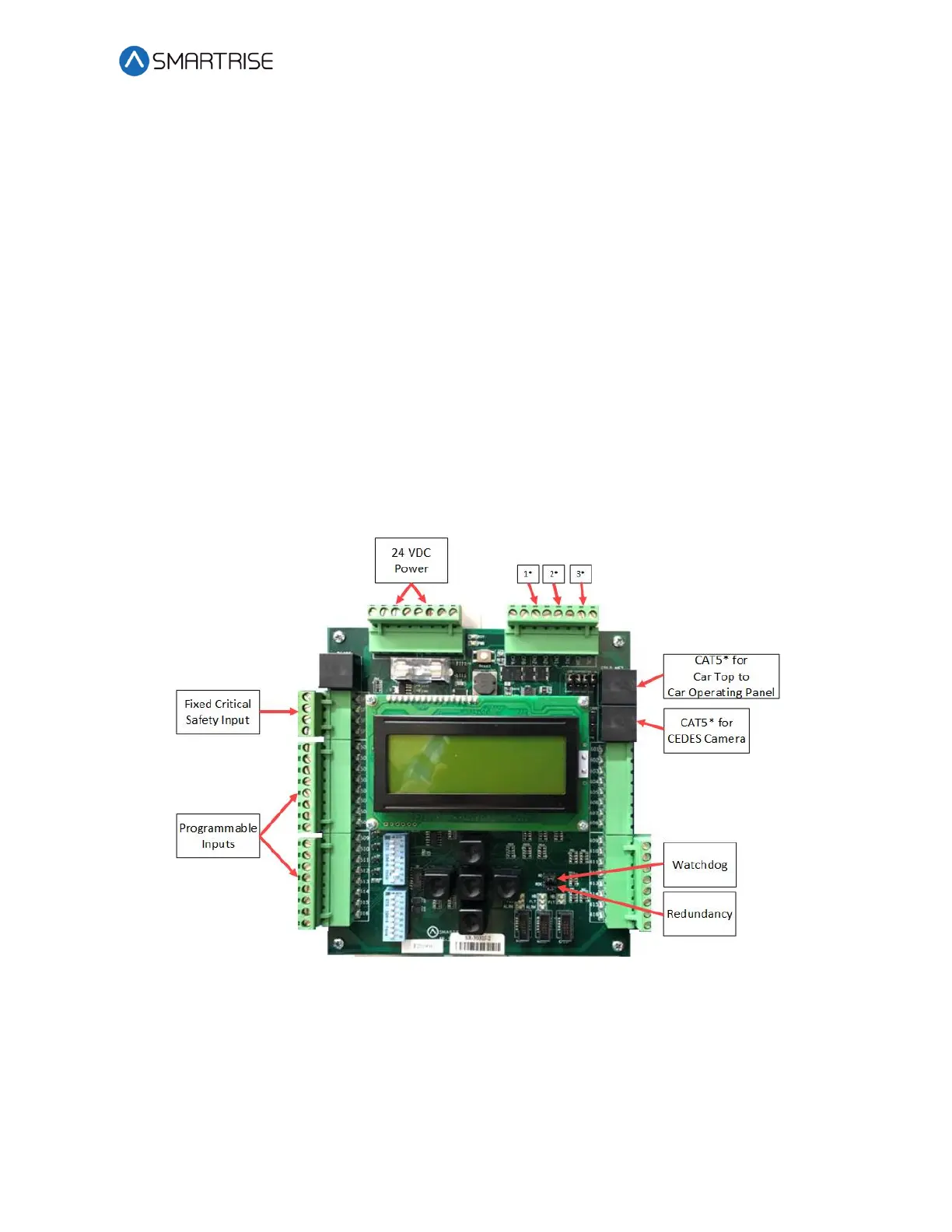
Figure 24: SRU Board SR3030
The serial communication is as follows:
• 1* (CN2+ CN2-) – Serial communication from the CT to the MR board for safety network.
• 2* (CN1+ CN1-) – Serial communication for devices on the car network.
• 3* (C3H and C3L) – Serial communication to third-party devices, for example, the fixture
driver board.
 Loading...

