Engine General Information and Diagnosis: 1A-41
DTC “C14” (P0120-H/L): TP Sensor Circuit Malfunction
B823H11104012
Detected Condition and Possible Cause
Wiring Diagram
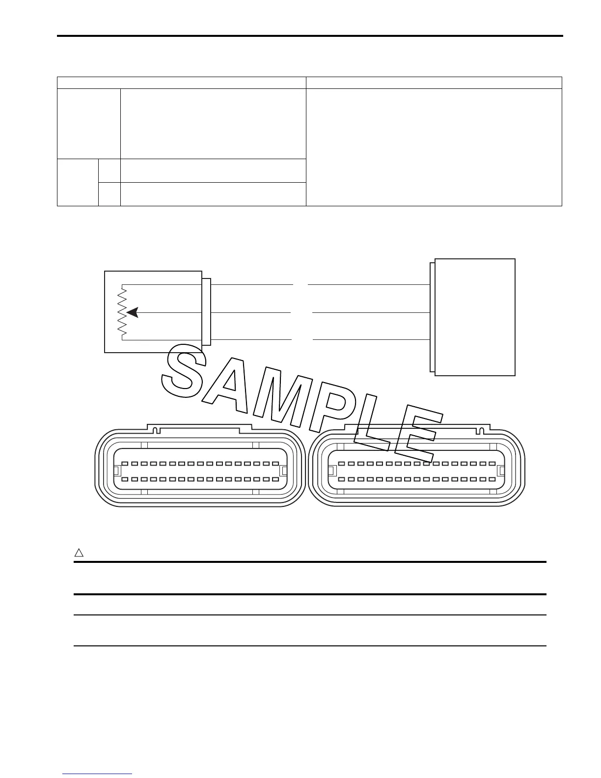
ECM coupler (Harness side)
Troubleshooting
CAUTION
!
When using the multi-circuit tester, do not strongly touch the terminal of the ECM coupler with a
needle pointed tester probe to prevent the terminal damage or terminal bend.
NOTE
After repairing the trouble, clear the DTC using SDS tool. Refer to “Use of SDS Diagnosis Reset
Procedures (Page 1A-14)”.
Detected Condition Possible Cause
C14
Output voltage is not within the following
range.
Difference between actual throttle opening
and opening calculated by ECM is larger
than specified value.
0.2 V d Sensor voltage < 4.8 V
• TP sensor maladjusted.
• TP sensor circuit open or short.
• TP sensor malfunction.
• ECM malfunction.
P0120
H
Sensor voltage is higher than specified
value.
• TP sensor circuit is shorted to VCC or ground circuit is
open.
L
Sensor voltage is lower than specified
value.
• TP sensor circuit is open or shorted to the ground or
VCC circuit is open.
ECM
R
B/Br
VCC
TPS
E2
P/B
TP sensor
11
8
29
I823H1110024-05
1 2 3 4 5 6 7 8 9 10 11121314151617
18
18 19 20 21 22 23 26 2724 25 28 29 30 31 32 33 34
35
36
37 38 39 40 41 42 43 44 45 46 47 48 49 50 51
53 54 55 56 57 58 59 60 61 62 63 6764 65 66 68

 Loading...


