5B-14 Manual Transmission:
Gearshift Lever Removal and Installation
B823H15206010
Removal
Remove the gearshift lever as shown in the gearshift
lever construction. Refer to “Gearshift Lever
Construction (Page 5B-13)”.
Installation
1) Install the gearshift lever as shown in the gearshift
lever construction. Refer to “Gearshift Lever
Construction (Page 5B-13)”.
2) After installing the gearshift lever, check the gearshift
lever height. Refer to “Gearshift Lever Height
Inspection and Adjustment (Page 5B-14)”.
Gearshift Lever Height Inspection and
Adjustment
B823H15206011
Inspect and adjust the gearshift lever height in the
following procedures:
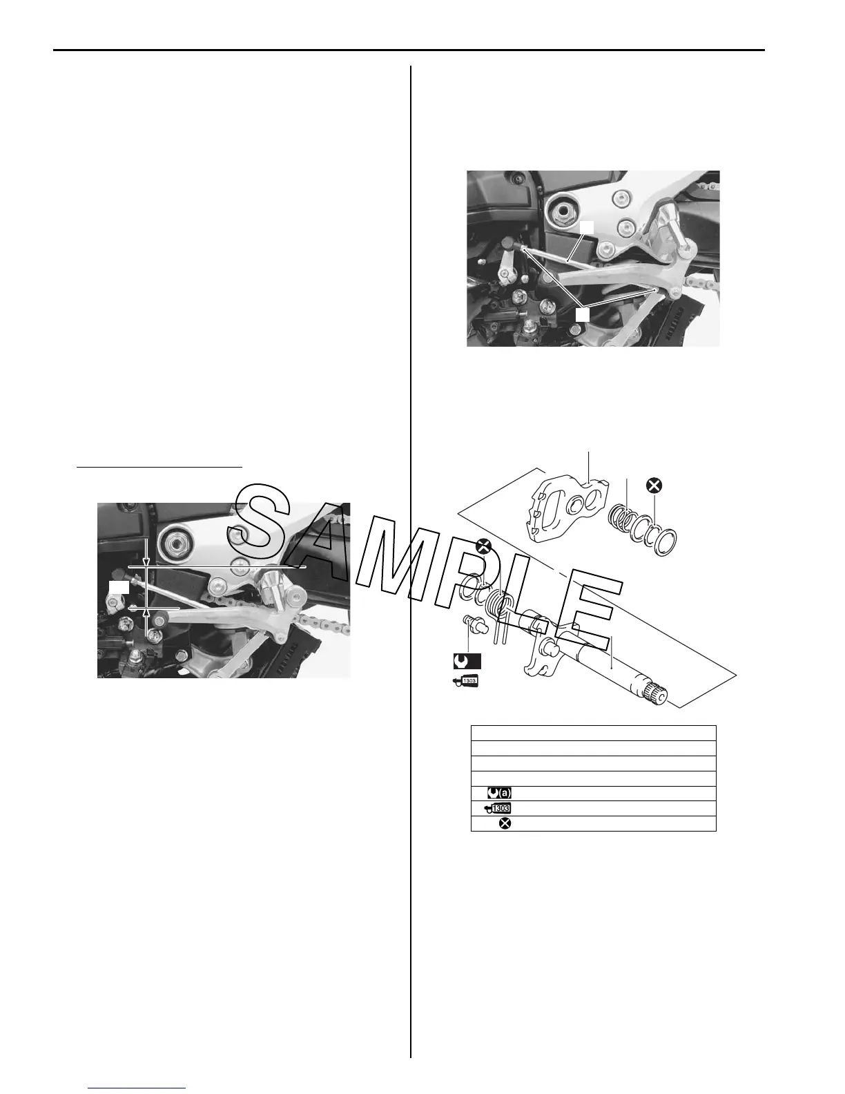
1) Inspect the gearshift lever height “a” between the
lever top and footrest.
Adjust the gearshift lever height if necessary.
Gearshift lever height “a”
Standard: 55 – 65 mm (2.2 – 2.6 in)
2) Loosen the lock-nuts (1).
3) Turn the gearshift link rod (2) until the gearshift lever
is 55 – 65 mm (2.2 – 2.6 in) below the top of the
footrest.
4) Tighten the lock-nuts securely.
Gearshift Shaft / Gearshift Cam Plate
Components
B823H15206012
“a”
I823H1520095-01
1. Gearshift shaft
2. Gearshift shaft return spring
3. Gearshift cam drive plate
4. Gearshift plate return spring
:19 Nm (1.9 kgf-m, 13.5 lb-ft)
: Apply thread lock to the thread part.
: Do not reuse.
1
2
I823H1520096-01
3
4
1
2
(a)
I823H1520097-01

 Loading...


