Combination Meter / Fuel Meter / Horn: 9C-3
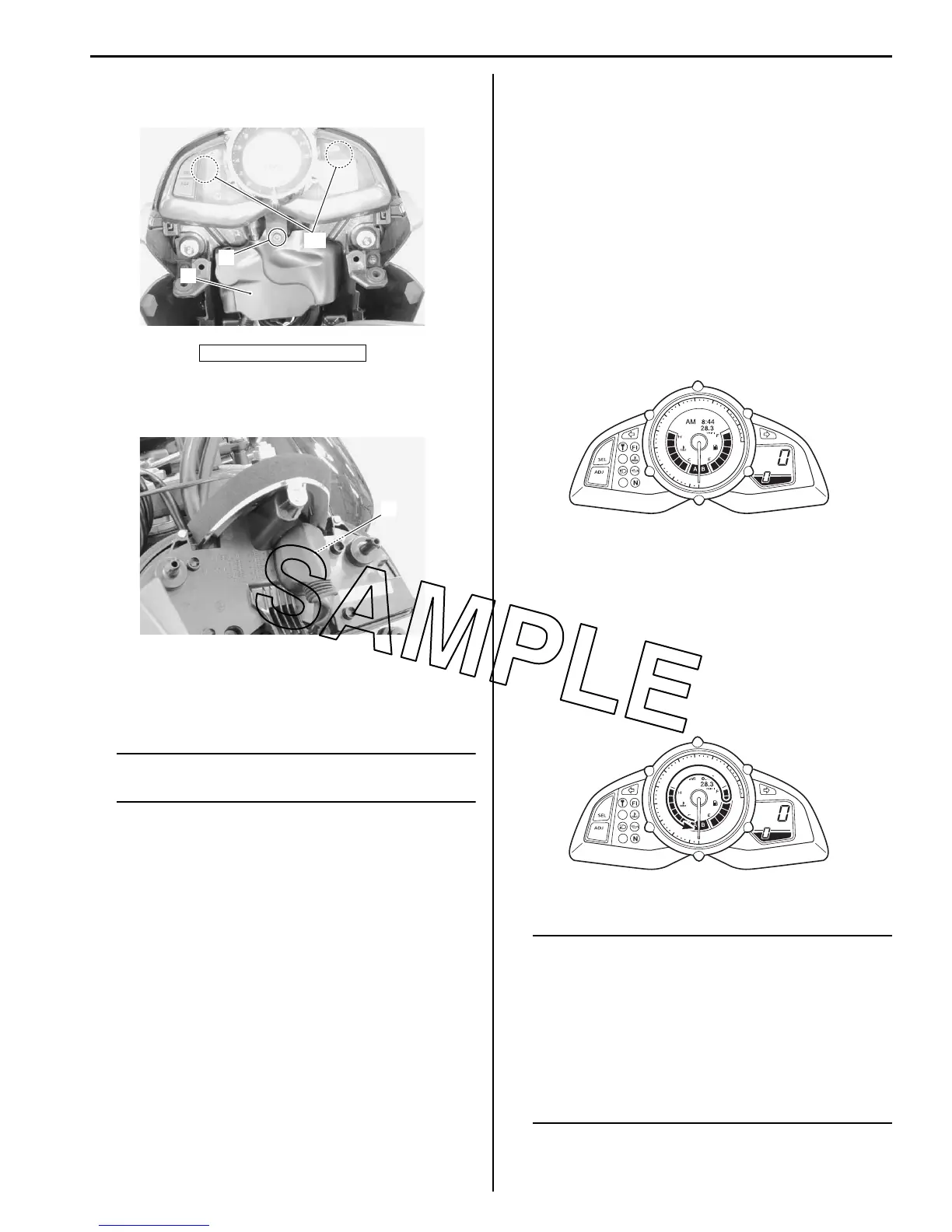
3) Remove the bolt (3) and pull out the combination
meter from the headlight cover (4).
4) Disconnect the combination meter coupler (5) and
remove the combination meter assembly.
Installation
Install the combination meter in the reverse order of
removal. Pay attention to the following point:
NOTE
Fix the boot of the combination meter
coupler properly.
• After installing, be sure to inspect the headlight beam.
Refer to “Headlight Beam Adjustment in Section 9B
(Page 9B-6)”.
Combination Meter Disassembly and Assembly
B823H19306003
Refer to “Combination Meter Removal and Installation
(Page 9C-2)”.
Disassembly
Disassemble the combination meter as shown in the
combination meter components. Refer to “Combination
Meter Components (Page 9C-2)”.
Assembly
Assemble the combination meter as shown in the
combination meter components. Refer to “Combination
Meter Components (Page 9C-2)”.
Combination Meter Inspection
B823H19306004
LED Inspection
Check that the LEDs (FI indicator light, Oil pressure,
Engine coolant temperature indicator light, Immobilizer
indicator light (For E-02, 19, 24), and Meter panel
illumination) immediately light up when the ignition
switch is turned to ON.
Check that other LEDs (Neutral indicator light, High-
beam indicator light and Turn signal indicator lights) light
up/go off by operating each switch.
If abnormal condition is found, replace the combination
meter assembly with a new one after checking its wire
harness/coupler. Refer to “Combination Meter Removal
and Installation (Page 9C-2)”.
Stepping Motor Inspection and Adjustment
1) Check that the pointer calibrates itself immediately
after turning the ignition switch on and stops at zero
point.
If abnormal condition is found, replace the
combination meter assembly with a new one after
checking its wire harness/coupler.
NOTE
• The pointer may not return to the proper
position even turning the ignition switch
on under low temperature condition. In
that case, you can reset the pointer to the
proper position by the following
instruction.
• Complete the operation within 10 seconds
after the ignition switch has been turned
on.
“A”: Hooked point
“A”
3
4
I823H1930029-02
5
I823H1930030-02
3
2
4
5
6
7
8
9
10
11
12
1
0
x1
00
0
r/m
in
km/h
I823H1930003-02
3
2
4
5
6
7
8
9
10
11
12
1
0
x
1
00
0
r/m
in
km/h
I823H1930004-03

 Loading...


