4A-2 Brake Control System and Diagnosis:
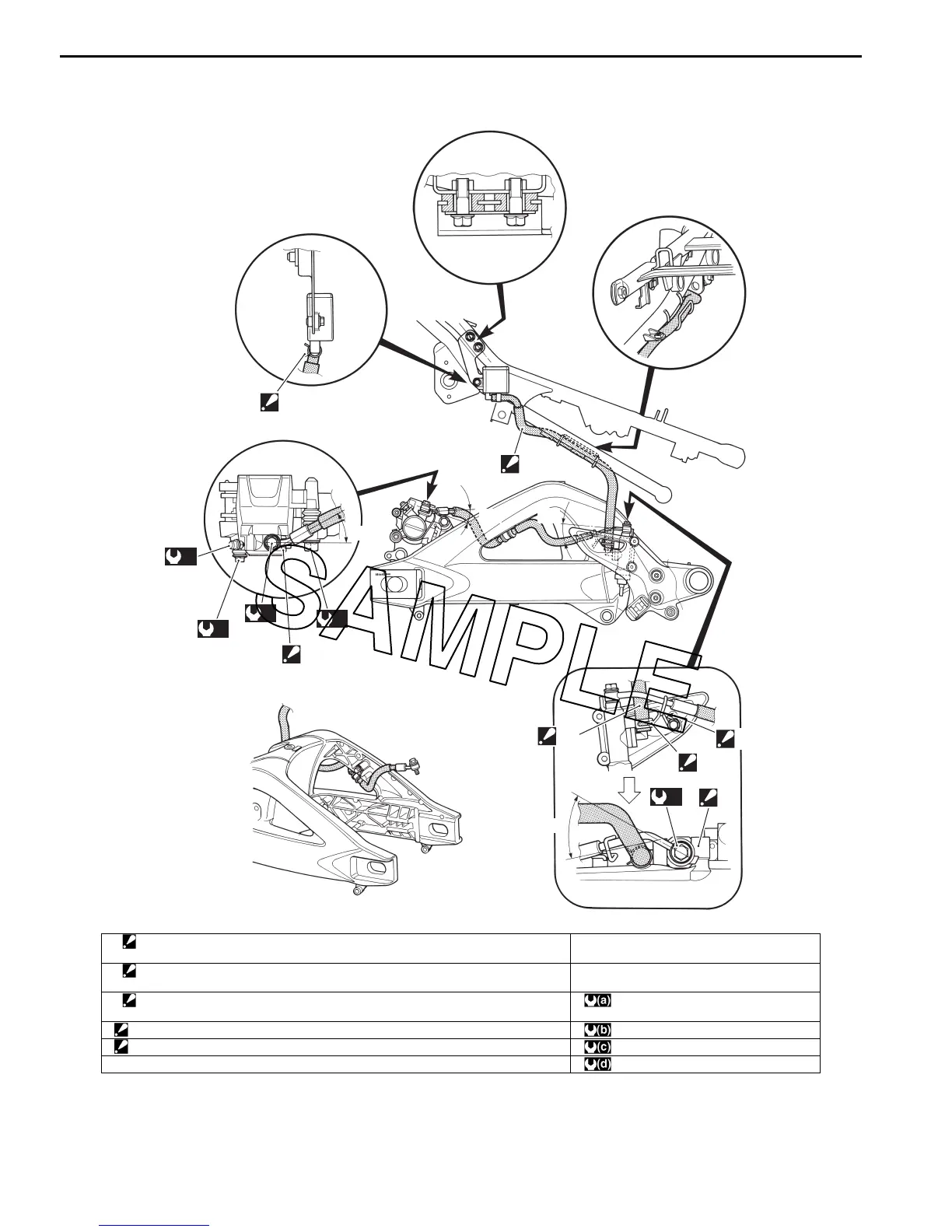
Rear Brake Hose Routing Diagram
B823H14102002
3
“A”
(b)
(c)
(a)
1
(d)
“a”
“b”
“a”
“A”
2
“B”
“c”
(a)
1
I823H1410049-03
1. Stopper
: After the brake hose union has contacted the stopper, tighten the union bolt.
“b”: 21q
2. Brake hose clamp
: Brake hose clamp ends should face backward.
“c”: 42q
3. Brake hose clamp
: Brake hose clamp ends should face inside.
: 23 Nm (2.3 kgf-m, 16.5 lb-ft)
“A”: Face the white paint mark to inside. : 7.5 Nm (0.75 kgf-m, 5.5 lb-ft)
“B”: Position the brake hose guide firmly. : 18 Nm (1.8 kgf-m, 13.0 lb-ft)
“a”: 28q : 33 Nm (3.3 kgf-m, 24.0 lb-ft)

 Loading...


