1J-10 Charging System:
Regulator / Rectifier Inspection
B823H11A06006
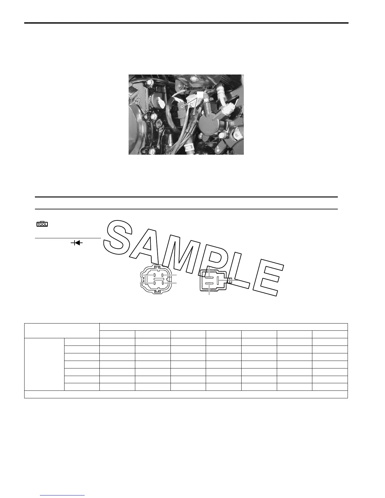
Inspect the regulator/rectifier in the following procedures:
1) Turn the ignition switch OFF.
2) Disconnect the regulator/rectifier couplers (1).
3) Measure the voltage between the terminals using the multi-circuit testers as indicated in the following table. If the
voltage is not within the specified value, replace the regulator/rectifier with a new one. Refer to “Regulator /
Rectifier Construction (Page 1J-9)”.
NOTE
If the tester reads 1.4 V and below when the tester probes are not connected, replace its battery.
Special tool
: 09900–25008 (Multi-circuit tester set)
Tester knob indication
Diode test ( )
Unit: V
4) Connect the regulator/rectifier couplers and bind the clamp.
1
I823H11A0019-01
B2
B3
B1
B/R2 B/W2
B/R1 B/W1
I823H11A0020-04
(+) probe of tester to:
B/R
1
B/R
2
B
1
B
2
B
3
B/W
1
B/W
2
(–) probe of
tester to:
B/R
1
— 0 0.1 – 0.8 0.1 – 0.8 0.1 – 0.8 0.2 – 0.9 0.2 – 0.9
B/R
2
0 — 0.1 – 0.8 0.1 – 0.8 0.1 – 0.8 0.2 – 0.9 0.2 – 0.9
B
1
* * — 0.5 – 1.2 0.5 – 1.2 0.1 – 0.8 0.1 – 0.8
B
2
* * 0.5 – 1.2 — 0.5 – 1.2 0.1 – 0.8 0.1 – 0.8
B
3
* * 0.5 – 1.2 0.5 – 1.2 — 0.1 – 0.8 0.1 – 0.8
B/W
1
* * 0.3 – 1.0 0.3 – 1.0 0.3 – 1.0 — 0
B/W
2
* * 0.3 – 1.0 0.3 – 1.0 0.3 – 1.0 0 —
*1.4 V and more (tester’s battery voltage)

 Loading...


