Starting System: 1I-13
Starter Button Inspection
B823H11906011
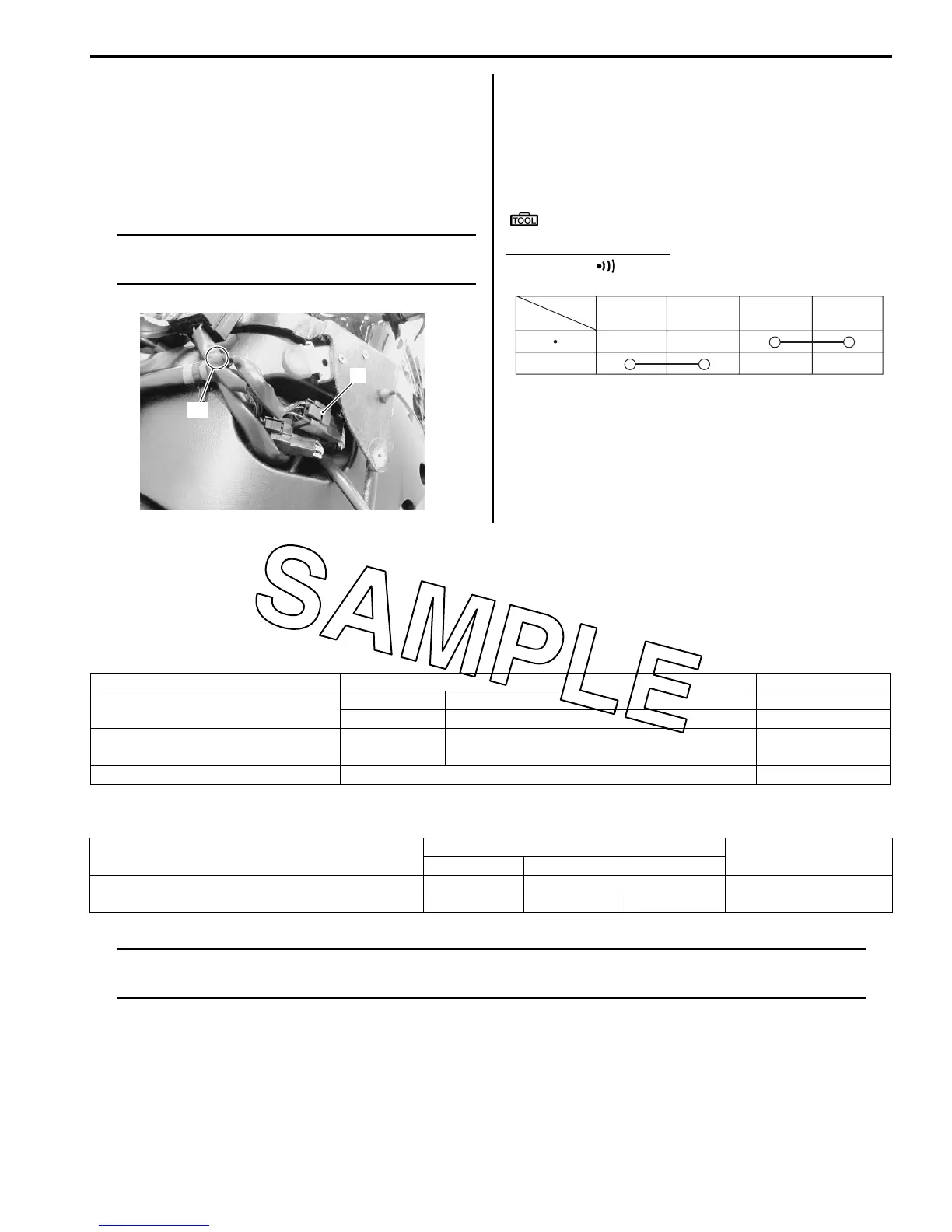
Inspect the starter button in the following procedures:
1) Remove the left fuel tank cover. Refer to “Exterior
Parts Removal and Installation in Section 9D
(Page 9D-14)”.
2) Disconnect the right handlebar switch coupler (1).
NOTE
Red tape “A” is sticked on the right handle
bar switch harness.
3) Inspect the starter button for continuity with the
tester.
If any abnormality is found, replace the right handle
switch assembly with a new one. Refer to
“Handlebar Removal and Installation in Section 6B
(Page 6B-3)”.
Special tool
: 09900–25008 (Multi-circuit tester set)
Tester knob indication
Continuity ( )
4) After finishing the starter button inspection, reinstall
the removed parts.
Specifications
Service Data
B823H11907001
Electrical
Unit: mm
Tightening Torque Specifications
B823H11907002
NOTE
The specified tightening torque is also described in the following.
“Starter Motor Components (Page 1I-3)”
Reference:
For the tightening torque of fastener not specified in this section, refer to “Tightening Torque List in Section 0C
(Page 0C-9)”.
1
“A”
I823H1190032-02
Position
Color
PUSH
B/R Bl/B B/Y
B/W
I718H1190040-01
Item Specification Note
Starter motor brush length
Standard 12.0 (0.47)
Limit 8.5 (0.33)
Starter torque limiter slip torque Standard
33.3 – 52.0 Nm
(3.3 – 5.2 kgf-m, 24.0 – 37.5 lb-ft)
Starter relay resistance 3 – 5 :
Fastening part
Tightening torque
Note
Nmkgf-mlb-ft
Starter motor housing bolt 5 0.5 3.5 )(Page 1I-5)
Starter clutch bolt 55 5.5 40.0 )(Page 1I-11)

 Loading...


