Combination Meter / Fuel Meter / Horn: 9C-9
Ignition Switch Inspection
B823H19306015
Inspect the ignition switch in the following procedures:
1) Lift and support the fuel tank. Refer to “Fuel Tank
Removal and Installation in Section 1G (Page 1G-
10)”.
2) Remove the air cleaner box. Refer to “Air Cleaner
Box Removal and Installation in Section 1D
(Page 1D-6)”.
3) Disconnect the ignition switch coupler (1).
4) Inspect the ignition switch for continuity with a tester.
If any abnormality is found, replace the ignition
switch with a new one.
Special tool
: 09900–25008 (Multi-circuit tester set)
Tester knob indication
Continuity ( )
E-02, 19, 24
E-03, 28, 33
5) After finishing the ignition switch inspection, reinstall
the removed parts.
Ignition Switch Removal and Installation
B823H19306016
Refer to “Ignition Switch Removal and Installation in
Section 1H (Page 1H-12)”.
Horn Inspection
B823H19306017
NOTE
If the horn sound condition is normal, it is not
necessary to inspect the horn button
continuity.
Horn Button Inspection
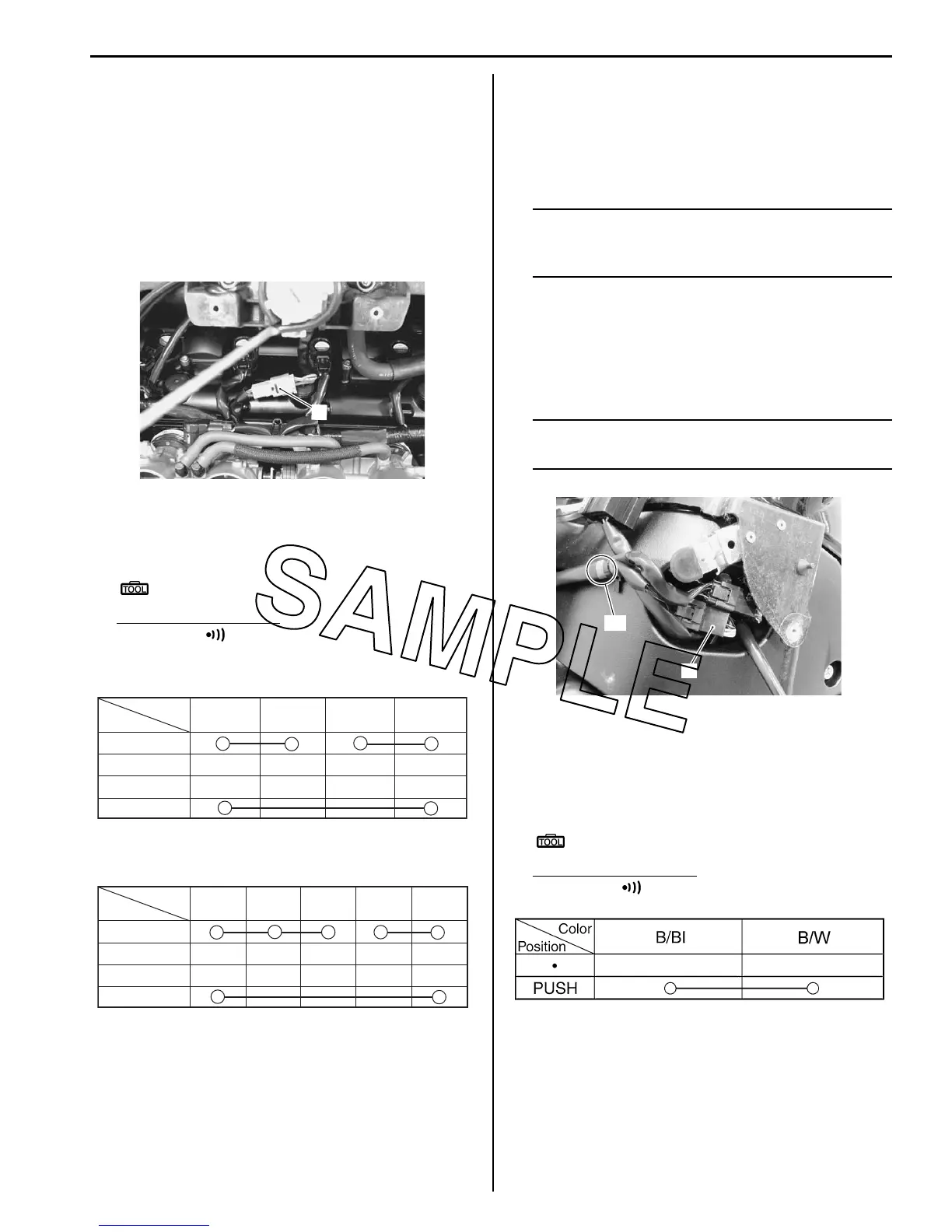
1) Remove the left fuel tank cover. Refer to “Exterior
Parts Removal and Installation in Section 9D
(Page 9D-14)”.
2) Disconnect the left handlebar switch coupler (1).
NOTE
Blue tape “A” is sicked on the left handle bar
switch harness.
3) Inspect the horn button for continuity with a tester.
If any abnormality is found, replace the left
handlebar switch assembly with a new one.
Refer to “Handlebar Removal and Installation in
Section 6B (Page 6B-3)”.
Special tool
: 09900–25008 (Multi-circuit tester set)
Tester knob indication
Continuity ( )
1
I823H1930018-01
P
LOCK
OFF
ON
R O Gr Br
Color
Position
I823H1930019-02
P
LOCK
OFF
ON
R O O/Y Gr Br
Color
Position
I823H1930020-02
“A”
1
I823H1930021-01
I718H1930028-03

 Loading...


