Engine Cooling System: 1F-11
Installation
Install the thermostat in the reverse order of removal.
Pay attention to the following points:
• Install the thermostat.
NOTE
The jiggle valve “A” of the thermostat faces
upside.
• Tighten the thermostat cover bolts (1) to the specified
torque.
Tightening torque
Thermostat cover bolt (a): 10 N·m (1.0 kgf-m, 7.0
lb-ft)
• Connect the water hoses securely. Refer to “Water
Hose Routing Diagram (Page 1F-3)”.
• Pour engine coolant and bleed air from the cooling
circuit. Refer to “Cooling System Inspection in Section
0B (Page 0B-13)”.
Thermostat Inspection
B823H11606014
Inspect the thermostat in the following procedures:
1) Remove the thermostat. Refer to “Thermostat Cover
/ Thermostat Removal and Installation (Page 1F-
10)”.
2) Inspect the thermostat pellet for signs of cracking.
3) Test the thermostat at the bench for control action.
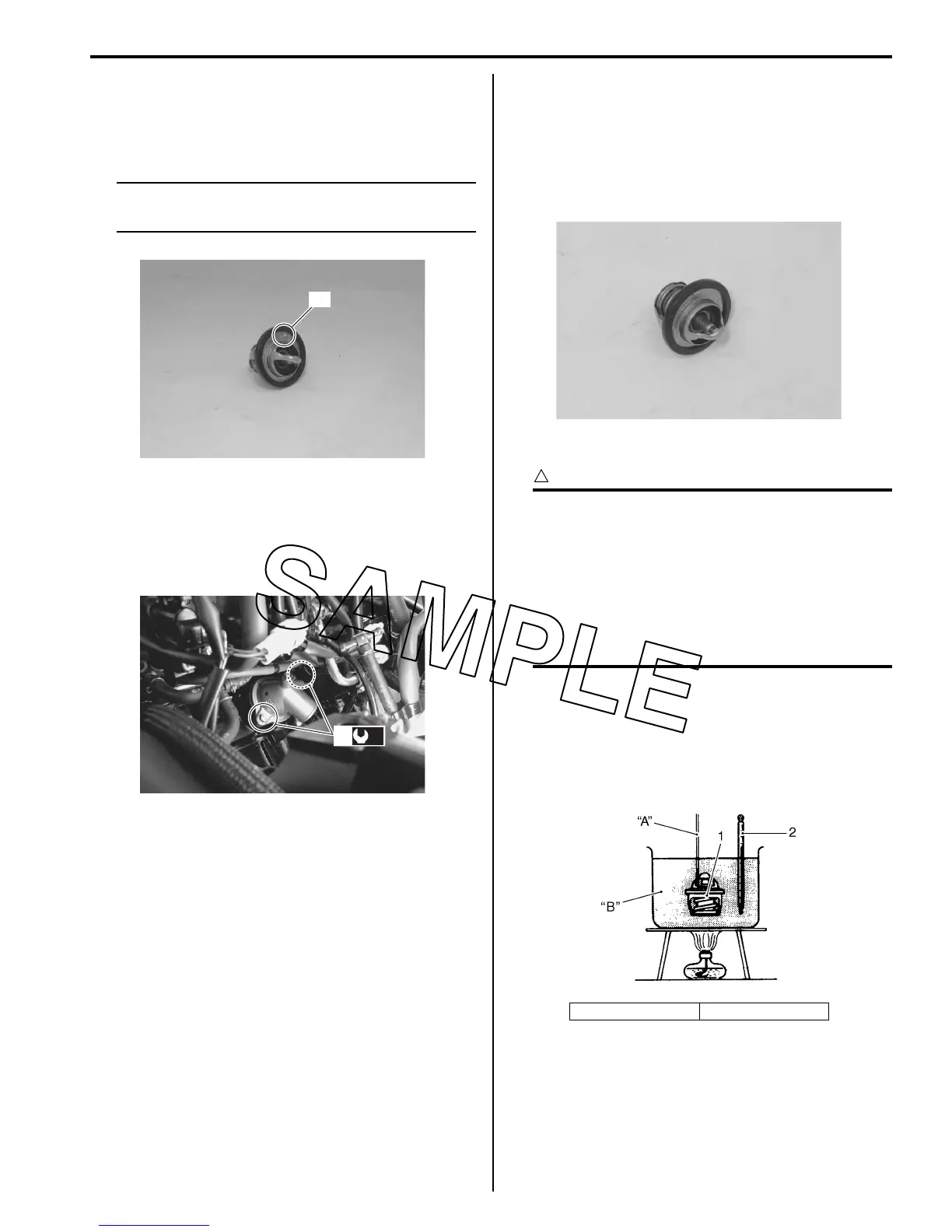
CAUTION
!
• Do not contact the thermostat (1) and
column thermometer (2) with a pan.
• As the thermostat operating response to
water temperature change is gradual, do
not raise water temperature too quickly.
• The thermostat with its valve open even
slightly under normal temperature must be
replaced.
4) Immerse the thermostat (1) in the water contained in
a beaker and note that the immersed thermostat is in
suspension.
5) Heat the water by placing the beaker on a stove and
observe the rising temperature on a thermometer
(2).
“A”
I823H1160025-01
(a)
1
I823H1160026-01
“A”: String “B”: Water
I823H1160027-01
I705H1160030-03

 Loading...


