1B-10 Emission Control Devices:
Installation
Install the HO2 sensor in the reverse order of removal.
Pay attention to the following points:
CAUTION
!
Do not apply oil or other materials to the
sensor air hole.
• Tighten the HO2 sensor (1) to the specified torque.
Tightening torque
HO2 sensor (a): 25 N·m (2.5 kgf-m, 18.0 lb-ft)
• Route the HO2 sensor lead wire properly. Refer to
“Wiring Harness Routing Diagram in Section 9A
(Page 9A-5)”.
Heated Oxygen Sensor (HO2S) Inspection
B823H11206002
Refer to “DTC “C44” (P0130/P0135): HO2 Sensor
(HO2S) Circuit Malfunction in Section 1A (Page 1A-
104)”.
PAIR Reed Valve Removal and Installation
B823H11206003
Removal
1) Lift and support the fuel tank. Refer to “Fuel Tank
Removal and Installation in Section 1G (Page 1G-
10)”.
2) Remove the air cleaner box. Refer to “Air Cleaner
Box Removal and Installation in Section 1D
(Page 1D-6)”.
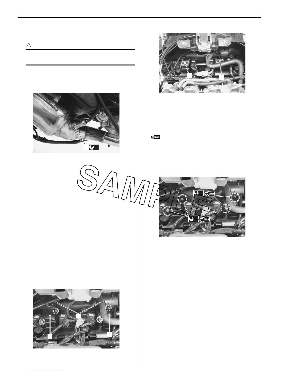
3) Disconnect the PAIR hoses (1) and remove the PAIR
reed valve covers (2).
4) Remove the PAIR reed valves (3).
Installation
Install the PAIR reed valve in the reverse order of
removal. Pay attention to the following points:
• Apply thread lock to the bolts and tighten them to the
specified torque.
: Thread lock cement 99000–32110
(THREAD LOCK CEMENT SUPER 1322 or
equivalent)
Tightening torque
PAIR reed valve cover bolt (a): 11 N·m (1.1 kgf-m,
8.0 lb-ft)
(a)
1
I823H1120007-03
1
2
2
I823H1120008-07
3
3
I823H1120009-02
(a)
(a)
I823H1120010-01

 Loading...


