1D-53 Engine Mechanical:
• Be sure that the rounded lip “K” of the cotter fits
snugly into the groove “L” in the stem end.
• Install the other valves and springs in the same
manner as described previously.
• Install the tappet shims and the tappets to their
original positions.
NOTE
• Apply engine oil to the stem end, shim and
tappet before fitting them.
• When seating the tappet shim, be sure the
figure printed surface faces the tappet.
Cylinder Head Related Parts Inspection
B823H11406027
Refer to “Cylinder Head Disassembly and Assembly
(Page 1D-48)”.
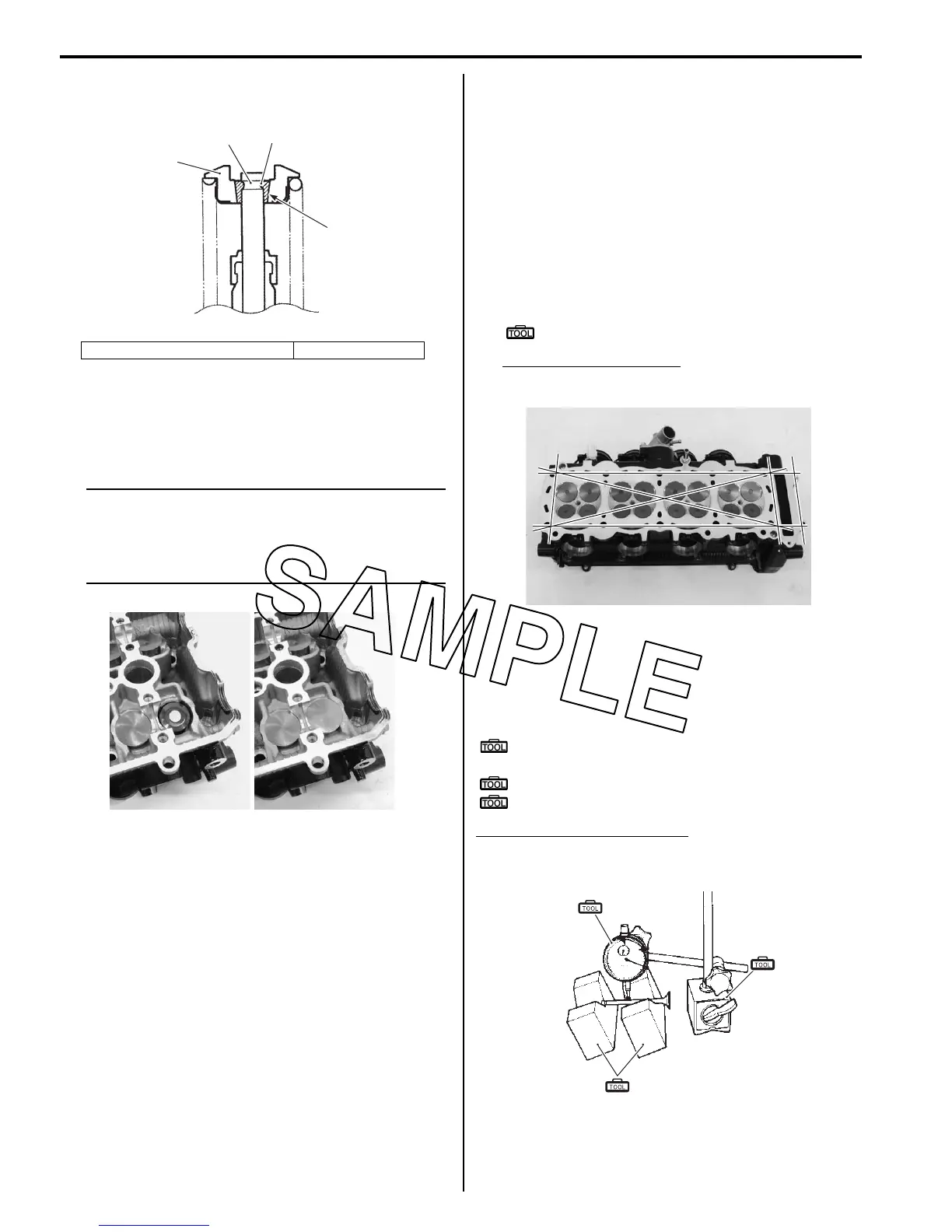
Cylinder Head Distortion
1) Decarbonize the combustion chambers.
2) Check the gasket surface of the cylinder head for
distortion. Use a straightedge and thickness gauge.
Take clearance readings at several places. If
readings exceed the service limit, replace the
cylinder head.
Special tool
: 09900–20803 (Thickness gauge)
Cylinder head distortion
Service limit: 0.20 mm (0.008 in)
Valve Stem Runout
Support the valve using V-blocks, as shown in the figure,
and check its runout using the dial gauge. If the runout
exceeds the service limit, replace the valve.
Special tool
(A): 09900–20607 (Dial gauge (1/100 mm, 10
mm))
(B): 09900–20701 (Magnetic stand)
(C): 09900–21304 (V-block (100 mm))
Valve stem runout (IN. & EX.)
Service limit: 0.05 mm (0.002 in)
8. Valve spring retainer 9. Cotter
“K”
8
9
“L”
I823H1140127-04
I823H1140389-01
I823H1140390-01
(A)
(C)
(B)
I649G1140231-03

 Loading...


