Combination Meter / Fuel Meter / Horn: 9C-5
4) Turn the ignition switch ON.
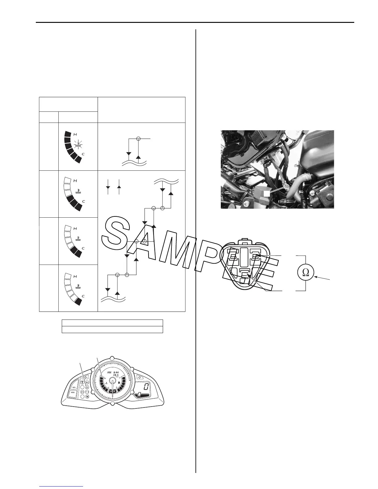
5) Check the engine coolant temperature indicator LCD
(3) and LED (4) operations when the resistance is
adjusted to the specified values.
If either one or all indications are abnormal, replace
the combination meter assembly with a new one.
Refer to “Combination Meter Removal and
Installation (Page 9C-2)”.
6) Connect the ECT sensor coupler.
7) Install the removed parts.
ECT Sensor Removal and Installation
B823H19306006
Refer to “ECT Sensor Removal and Installation in
Section 1C (Page 1C-5)”.
Fuel Level Indicator Inspection
B823H19306007
Inspect the fuel level indicator in the following
procedures:
1) Lift and support the fuel tank. Refer to “Fuel Tank
Removal and Installation in Section 1G (Page 1G-
10)”.
2) Disconnect the fuel pump coupler (1).
3) Connect a variable resistor (2) between the B/Lg and
B/W lead wires of the wire harness side coupler.
4) Turn the ignition switch ON.
5) Check the display of fuel level indicator (LCD) as
shown in the figure.
If any abnormality is found, replace the combination
meter with a new one. Refer to “Combination Meter
Removal and Installation (Page 9C-2)”.
“A”: When decreasing the temperature
“B”: When increasing the temperature
Flicker
LED LCD
ON
OFF
OFF
OFF
Engine coolant
temperature indicator
ON
ON
ON
50 °C
(122 °F)
Approx.
0.811 kΩ
70 °C
(158 °F)
Approx.
0.428 kΩ
110 °C
(230 °F)
Approx.
0.184 kΩ
41 °C
(106 °F)
Approx.
1.15 kΩ
51 °C
(124 °F)
Approx.
0.811 kΩ
71 °C
(160 °F)
Approx.
0.428 kΩ
Temperature and resistance
120 °C
(248 °F)
Approx.
0.111 kΩ
“A” “B”
I823H1930032-09
3
2
4
5
6
7
8
9
10
11
12
1
0
x1
0
0
0
r/m
in
km/h
4
3
I823H1930007-03
1
I823H1930009-01
B/Lg
B/W
2
I823H1930010-03

 Loading...


