Engine Lubrication System: 1E-11
Installation
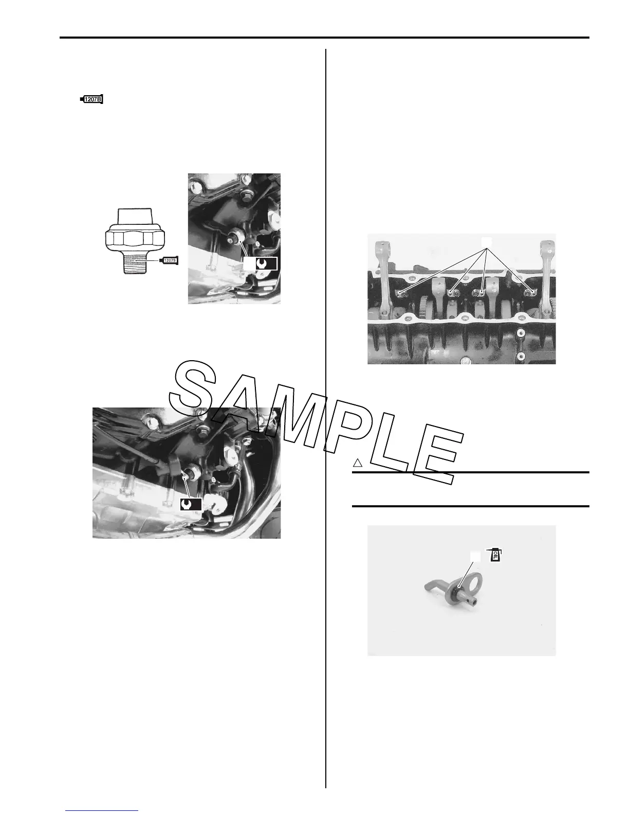
1) Install the oil pressure switch (1), apply a bond lightly
to its thread and tighten it to the specified torque.
: Sealant 99000–31140 (SUZUKI Bond
1207B or equivalent)
Tightening torque
Oil pressure switch (a): 14 N·m (1.4 kgf-m, 10.0
lb-ft)
2) Connect the oil pressure switch lead wire securely.
Refer to “Wiring Harness Routing Diagram in
Section 9A (Page 9A-5)”.
Tightening torque
Oil pressure switch lead wire bolt (b): 1.5 N·m (
0.15 kgf-m, 1.1 lb-ft)
3) Pour engine oil. Refer to “Engine Oil and Filter
Replacement in Section 0B (Page 0B-10)”.
4) Install the removed parts.
Oil Pressure Switch Inspection
B823H11506007
Refer to “Oil Pressure Indicator Inspection in Section 9C
(Page 9C-8)”.
Oil Jet / Oil Gallery Jet Removal and Installation
B823H11506008
Oil Jet (For Pistons)
Removal
1) Remove the engine assembly. Refer to “Engine
Assembly Removal in Section 1D (Page 1D-19)”.
2) Remove the Cylinder. Refer to “Engine Top Side
Disassembly in Section 1D (Page 1D-28)”.
3) Remove the piston cooling oil jets (1).
Installation
Installation is in the reverse order of removal. Pay
attention to the following points:
• Fit the new O-ring (1) to each piston cooling oil jet and
apply engine oil to them.
CAUTION
!
Use the new O-rings to prevent oil pressure
leakage.
(a)
1
I823H1150046-02
(b)
I823H1150016-01
1
I823H1150032-02
1
I823H1150033-01

 Loading...


