Brake Control System and Diagnosis: 4A-1
Brake
Brake Control System and Diagnosis
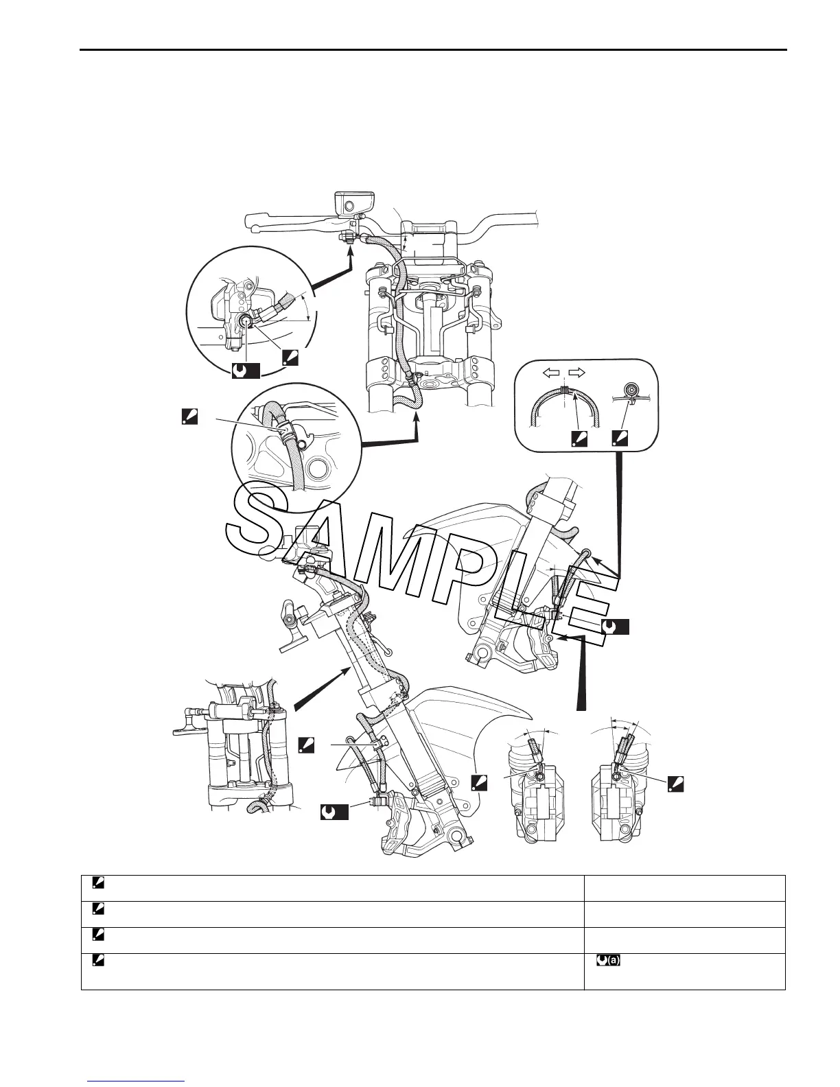
Schematic and Routing Diagram
Front Brake Hose Routing Diagram
B823H14102001
“a”
“b”
“a”
LH RH
3
1
2
(a)
(a)
“c”
“b”
1
1
“a”
(a)
2
4
“b”
I823H1410047-02
1. Stopper
: After the brake hose union has contacted the stopper, tighten the union bolt.
“a”: 21q
2. Hose guide
: Fit the grommet sleeve on the brake hose to the hose guide properly.
“b”: 28q
3. Brake hose clamp
: Insert the clamp to the hole of the front fender fully.
“c”: 35q
4. Green paint marking
: Locate the green paint marking on the brake hose No. 2 to the right side of the brake hose clamp and it
faces top side.
: 23 Nm (2.3 kgf-m, 16.5 lb-ft)

 Loading...


